Flow Controller

The Homebrew Forum

Help Support The Homebrew Forum:

This site may earn a commission from merchant affiliate links, including eBay, Amazon, and others.
I automated my brewery a couple of years back using Visual Basic to control a digibee+, which in turn operates three peristaltic pumps, a marchmay mmp3 pump (for the RIMs), a stick heater (rims), various kettle elements, a flip shelf(that the hop rockets sits on), a counter flow chiller valve (I use the very same electric valve you pictured) and four solonoid s that operate the hop hoppers! Temps are via analog inputs. Took some time to get it all working but works well.

However, I bought a RaspberryPi a few weeks back and installed it at my holiday home in France to upload one wire temperature sensors and it is working well...trouble is now I want to upgrade my AutoBrew Mk1 to Mk2 now! First step is moving from analog temp inputs to digital ones......

Good luck with the automation!

Steve
 
Belter said:
I use a din rail mounted 24v panel power supply in my electric brewery panel. I doubt you'd ever get anywhere near 20A. Solar pumps are 1A. SoLard pumps are 3A. Pids are mili amps. I had a 5A supply running everything then future proofed by going up to 10A.

Cheers, I'll go for a 10A one then, shaves a bit of cash off. Down the line I'm thinking of building a control panel and am definitely considering DIN rails but for the moment one of these should suffice.

EccentricDyslexic said:
I automated my brewery a couple of years back using Visual Basic to control a digibee+, which in turn operates three peristaltic pumps, a marchmay mmp3 pump (for the RIMs), a stick heater (rims), various kettle elements, a flip shelf(that the hop rockets sits on), a counter flow chiller valve (I use the very same electric valve you pictured) and four solonoid s that operate the hop hoppers! Temps are via analog inputs. Took some time to get it all working but works well.

However, I bought a RaspberryPi a few weeks back and installed it at my holiday home in France to upload one wire temperature sensors and it is working well...trouble is now I want to upgrade my AutoBrew Mk1 to Mk2 now! First step is moving from analog temp inputs to digital ones......

That's fairly hardcore automation, well done :) Any shots of it in action?

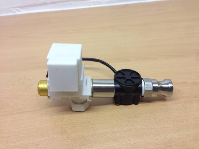
I've assembled the components for a quick test:

JxnD5Pm.jpg


I don't have any way of controlling the solenoid yet as the relays haven't arrived but figured I could test using the bypass for the moment until I get everything setup just to see what it thinks 10 litres of water comes to.
 
Flow meters or solenoids? Judging by the eBay description of the solenoid I'd say yes. Not sure about flow meters


Edit: flow meters for water vending so fine.
 
flow meters are ok upto 80c and suitable for drinks so fingers crossed, the rather yellow brass on the valves did raise my eyebrows but the ad stated suitable for pottable water systems. so for brewing liquor and hlt use should be fine, on the post mash side of things my jury is still out....
yellow brass questions ??

measuring the flow to the valve rather than post valve eh steve? (assuming the valve filter is on the input to protect the valve??)
 
Cyclops said:
You could pickle the brass to reduce the amount of things that could leach out of it :)

ok i will bite ;)
is that an acid bath? if so whats available on the domestic market to do the job??
 
EccentricDyslexic said:
I automated my brewery a couple of years back using Visual Basic to control a digibee+, which in turn operates three peristaltic pumps, a marchmay mmp3 pump (for the RIMs), a stick heater (rims), various kettle elements, a flip shelf(that the hop rockets sits on), a counter flow chiller valve (I use the very same electric valve you pictured) and four solonoid s that operate the hop hoppers! Temps are via analog inputs. Took some time to get it all working but works well.

However, I bought a RaspberryPi a few weeks back and installed it at my holiday home in France to upload one wire temperature sensors and it is working well...trouble is now I want to upgrade my AutoBrew Mk1 to Mk2 now! First step is moving from analog temp inputs to digital ones......

That's fairly hardcore automation, well done :) Any shots of it in action?
[/quote]

Yes I have some clips, but really want to do a proper video for YouTube with text explanations etc. of the whole process start to finish. I am brewing on Wednesday coming so will take a more through video!

Steve
 
Fil said:
measuring the flow to the valve rather than post valve eh steve? (assuming the valve filter is on the input to protect the valve??)

I thought this way round would be the best to cope with the lag that you said was present in closing the valve. May have to experiment both ways round and see if there is any difference.

I've ordered a 10A psu so as soon as the relays arrive I can start putting all this together, I'll add the code this weekend for the solenoid in case anyone else is ready to go, shouldn't be much more than setting one of the digital pins to high/low though.
 
I tend to agree with you putting the low meter down line. The sensor will pick up the flow, so it needs to be as near the receiving vessel as possible to ensure the liquid that has passed the sensor drains down to the vessel. Although in practice this could be accounted for if the liquid in the pipework was measured and constant. My bits have yet to arrive so I am a bit behind you guys. I ordered the ready made one and a uno so if it works I have a choice for the future. The uno should arrive this week, but the other bits will probably take a couple of weeks from China.
 
OK I've quickly added some code to handle the solenoid but without the relays I can't prove if this works. I believe these relays are active low, so have coded that way round, if not just swap the HIGH and LOW values in the digitalWrite(SOLENOIDPIN) calls.

The left button has now been remapped as a start button, pressing this should open the solenoid so that there are no nasty accidents :)

Code:
////////////////////////////////////////////////////////////////////////////
//                           BrewShark v1                                 //
// Change value of hltSIZE to match the max volume in your HLT            //  
//                                                                        //
////////////////////////////////////////////////////////////////////////////

#include <LiquidCrystal.h>

LiquidCrystal lcd(8, 9, 4, 5, 6, 7);

int lcd_key     = 0;
int adc_key_in  = 0;
float target_volume = 23;
float current_volume = 0;

#define btnRIGHT  0
#define btnUP     1
#define btnDOWN   2
#define btnLEFT   3
#define btnSELECT 4
#define btnNONE   5

#define hltSIZE   50                       //Size of the Hot Liquor Tun in litres

#define SOLENOIDPIN 1
#define FLOWSENSORPIN 2

// count how many pulses
volatile uint16_t pulses = 0;
// track the state of the pulse pin
volatile uint8_t lastflowpinstate;
// you can try to keep time of how long it is between pulses
volatile uint32_t lastflowratetimer = 0;
// and use that to calculate a flow rate
volatile float flowrate;
// Interrupt is called once a millisecond, looks for any pulses from the sensor!
SIGNAL(TIMER0_COMPA_vect) {
  uint8_t x = digitalRead(FLOWSENSORPIN);
  
  if (x == lastflowpinstate) {
    lastflowratetimer++;
    return; // nothing changed!
  }
  
  if (x == HIGH) {
    //low to high transition!
    pulses++;
  }
  lastflowpinstate = x;
  flowrate = 1000.0;
  flowrate /= lastflowratetimer; // in hertz
  lastflowratetimer = 0;
}

void useInterrupt(boolean v) {
  if (v) {
    // Timer0 is already used for millis() - we'll just interrupt somewhere
    // in the middle and call the "Compare A" function above
    OCR0A = 0xAF;
    TIMSK0 |= _BV(OCIE0A);
  } else {
    // do not call the interrupt function COMPA anymore
    TIMSK0 &= ~_BV(OCIE0A);
  }
}

void setup()
{
    
  Serial.begin(9600);
  Serial.print("Flow sensor test!");
  
  digitalWrite(FLOWSENSORPIN, HIGH);
  digitalWrite(SOLENOIDPIN,HIGH); //ACTIVE LOW RELAY PUT THIS FIRST TO ENSURE PIN IS IN CORRECT STATE BEFORE WE INIT IT
  
  pinMode(FLOWSENSORPIN, INPUT);
  pinMode(SOLENOIDPIN, OUTPUT);
  
  lcd.begin(16, 2);                        // start the library

  printBanner(2000);                       // show banner for 2 seconds
  
  clearLCD();
  
  printLabels();
  
  lastflowpinstate = digitalRead(FLOWSENSORPIN);
  useInterrupt(true);

}

void loop()
{

  while(current_volume < target_volume)
  { 
    dowork();
  }

  lcd.setCursor(0,0);
  lcd.print("  VALVE CLOSED  ");
  lcd.setCursor(0,1);
  lcd.print("   TARGET HIT   ");
  
  digitalWrite(SOLENOIDPIN,HIGH);      //Close solenoid
}

void clearLCD()
{
  lcd.setCursor(0,0);                      
  lcd.print("                ");
  lcd.setCursor(0,1);
  lcd.print("                ");
}

void printBanner(int bannerdelay)
{
  lcd.setCursor(0,0);                     
  lcd.print("        ^       ");
  lcd.setCursor(0,1);  
  lcd.print("  >=BrewShark>  ");
  delay(bannerdelay);
}

void printLabels()
{
  lcd.setCursor(0,0);
  lcd.print("Set Vol: ");
  lcd.setCursor(0,1);
  lcd.print("Cur Vol: ");
}

// read the buttons
int read_LCD_buttons()
{
  adc_key_in = analogRead(0);
  if (adc_key_in > 1000) return btnNONE;
  if (adc_key_in < 50)   return btnRIGHT; 
  if (adc_key_in < 195)  return btnSELECT;
  if (adc_key_in < 380)  return btnUP;
  if (adc_key_in < 555)  return btnDOWN;
  if (adc_key_in < 790)  return btnLEFT;  

  return btnNONE;
}

void dowork()
{

  Serial.print("Freq: "); Serial.println(flowrate);
  Serial.print("Pulses: "); Serial.println(pulses, DEC);
  float liters = pulses;
  liters /= 7.5;
  liters /= 60.0;
  
  current_volume = liters;
  
  //Print the target volume value in litres
  lcd.setCursor(11,0);
  lcd.print(target_volume,2);
  lcd.setCursor(15,0);
  lcd.print("L");

  //Print the current volume value in litres
  lcd.setCursor(11,1);            
  lcd.print(current_volume,2);
  lcd.setCursor(15,1);
  lcd.print("L");

  lcd_key = read_LCD_buttons();    // read the buttons
  

  switch (lcd_key)               // depending on which button was pushed, we perform an action
  {
  case btnRIGHT:
    {
      current_volume += 0.01;       //manually simulate flow
      break;
    }

  case btnLEFT:
    {
      digitalWrite(SOLENOIDPIN,LOW);       //START FLOW
      break;
    }

  case btnUP:
    {
      if (target_volume >= hltSIZE)  //don't go larger than the size of the vessel
      {
        target_volume = hltSIZE;
        break;
      }
      else
      {
        target_volume += 0.1;
        break;
      }

      break;
    }

  case btnDOWN:
    {
      if (target_volume <= 0)      //don't go below zero
      {
        target_volume = 0;
        break; 
      }
      else
      {
        target_volume -= 0.1;
      }
      break;
    }

  case btnNONE:
    {
      break;
    }
  }

}

Cheers

Steven
 
Cheers, I've also put a link to the download zip at the top of the first post as well so you don't have to hunt round the thread to find it.
 
Yeah thanks for keeping us updated. When my kit arrives I'll give it a download and try it out :)
 
Did someone say if you plugged a power supply into it the Arduino would output 12v? I take it you need the Arduino to trigger it to prove functionality? Otherwise just connect the + and - to your 12v power supply and it will open. I assume you know that already though.
 
The Arduino will take 7 - 12v as an input voltage, the digital IO pins are 5v at a max of 40mA which is why the relay board is needed.

Yeah I should probably test the valve by itself but all my 12v power supplies are wired into something already and I'm feeling lazy, I'll wait till I've got everything and test at once :)
 
so if u hook your board upto a 12v psu the power in + and - terminals will carry a 12v supply at the psu amp rating which u can take of to drive 12v components, switching via a relay with the gpio pins with the 5v opperating vlotage..

when prototyping use 1 side rail of the breadboard for source psu, and the other for board voltage ;) i then used a marker pen to write 12v and 5v respectivly on the breadboard.. saves blowing 5v components late at night that does..
 
Back
Top