Introduction
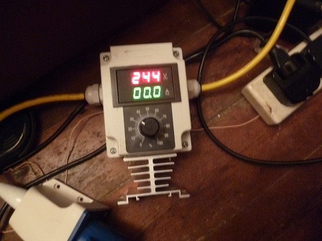
This digital power regulator is the high power equivalent of a dimmer switch for a light. It regulates the current delivered to your heating element by performing phase-angle control on the mains sine wave. By regulating the intensity of your boil you can control your losses through boil-off, save money on the electricity needed and ultimately produce more beer from your brewday.
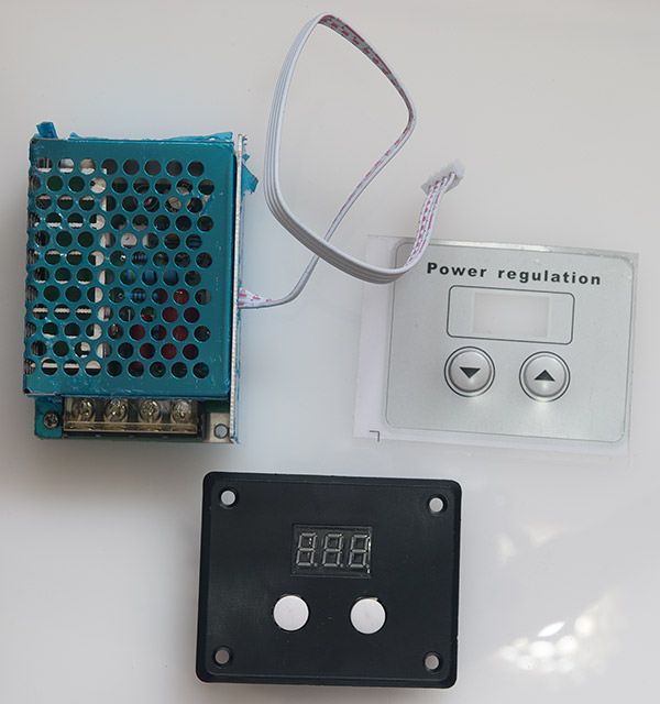
To build my power regulator I will use this module from ebay:

The listing states that it can control up to 4kW but only 2kW is recommended for long term use. I took it apart to find out the limiting factors.
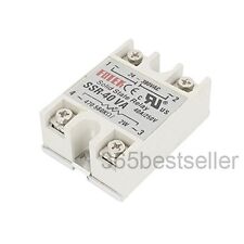
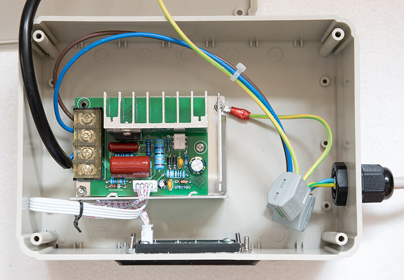
The phase-angle control is performed using a triac, in this case the BTA41600B from ST Micro. This is quite a substantial triac that can handle up to 41A of continuous current at up to 600V. In practice you are limited by how well you can cool the triac and in this unit it is screwed to a decent looking aluminium heatsink using thermal transfer compound.
The worst case thermal scenario for a triac is when it's held fully on. The BTA41600B has a maximum on-state resistance of 10mOhm which at 2kW/240V load will result in a power dissipation from the triac of 7W (see AN2703). That doesn't sound like a lot but it's easily enough to destroy the triac if no heatsinking was provided.
In operation the circuit works like this. We start with the triac off and no current flows. The mains sine wave drops through zero on the X axis and a detection circuit on this board sends a pulse to a cheap Atmel 8-bit microcontroller housed on the external display board. The micro starts a timer with a duration inversely proportional to the selected power percentage. When the timer expires the micro sends a current pulse of sufficient magnitude to turn on the triac and of sufficient length to cause the triac to latch on. Power is now being delivered to your heating element. At the next zero-crossing the triac automatically switches off, the detection circuit sends another pulse to the micro and the sequence starts again. This is all happening 100 times per second.
Now you know how it works, here's how to build one.
Parts required
The controller pictured above from ebay. It should cost less than a fiver from China. Search ebay for "4kW power regulator"
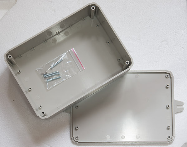
A suitable box that is going to protect you from sticking your fingers where they don't belong. Mine is 170x125x70mm (L/W/D) and I reckon it's about the perfect size. You can buy them on ebay or you may already have something suitable at home. This box will house dangerous mains voltages so don't be tempted to go for a flimsy solution.

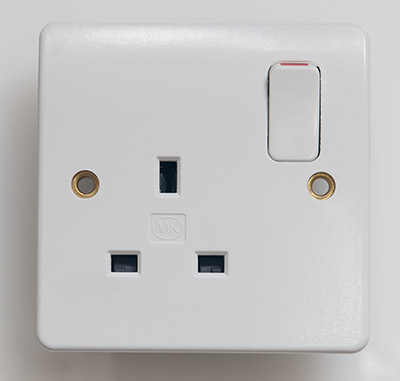
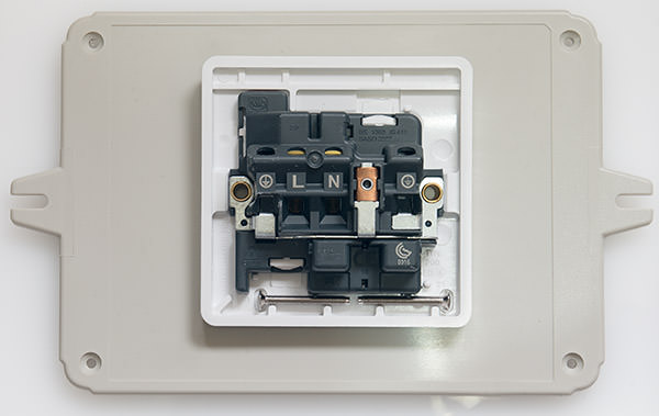
A 1-gang wall socket (available everywhere).

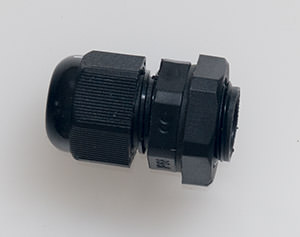
A cable gland (ebay search "cable gland").

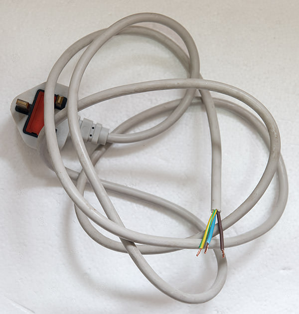
A length of 3-core mains cable rated for at least 10A with a wall plug on the end. A donor 'kettle lead' is ideal if you chop off the IEC connector leaving a length of wire with a mains plug on it.

3 cable connectors, e.g. chocolate blocks or similar. The connectors I've used are available on ebay. Search "3 way cable connector".
8 M3 screws of about 15mm with nuts.
1 Ring-type wire crimp connector for M3 screws.
Tools required
Oscillating multi-tool or other means of cutting large openings in plastic
Hand file
Drill
Screwdriver
Needle nose pliers (optional)
Multimeter (optional)
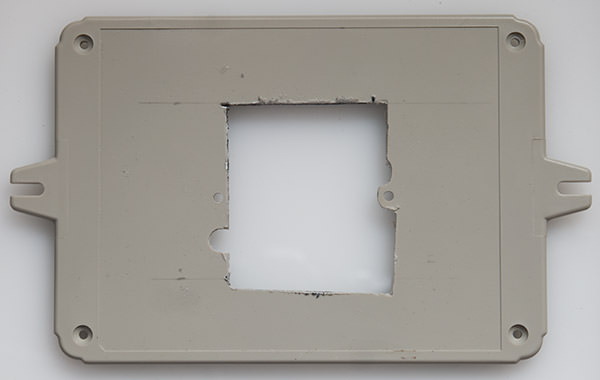
Step 1: Cut an opening for the socket.
The wall socket will be positioned on the lid of the box. Offer it up to the lid and mark where the first screw hole will be. Drill a hole for the screw. Now mark where the other screw will be and drill that.

Now the hard part. Work out how much you need to cut away to make the socket fit flush with the lid. You will probably have to come quite close to the screw holes. Take care to ensure that you don't come so close that the plastic cracks. Use your multi-tool to do the bulk of the cutting and finish off with a file.

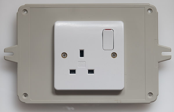
The screws supplied with the socket will probably be too long and in any case won't have nuts so use two of your M3 screws and nuts to secure the socket to the lid.

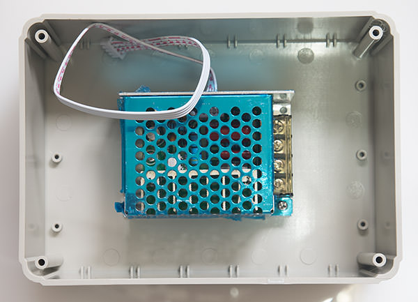
Step 2: Planning component locations
Work out where the controller will sit and where the mains entry hole will be. I left some space on the heatsink side of the controller in case I needed to come back later and fit a cooling fan.

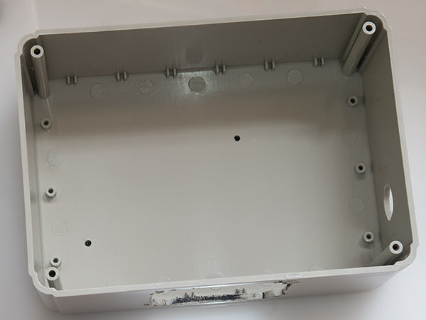
Step 3: Cut the remaining openings
The controller has space for two screws to be fitted to hold it to the base. Mark where they will be and drill holes for them.
Drill a large hole for the cable gland. If you don't have a hole-saw bit then use the biggest normal bit that you have and use a round file to enlarge it to the size you need. Go steady with the file, it's all too easy to end up with an oval shape that doesn't get completely covered by the gland.
Work out where you want the digital display to be then mark and drill the four holes that it requires. Now cut the opening using your multi-tool and a file to finish the job.

Step 4: Wiring
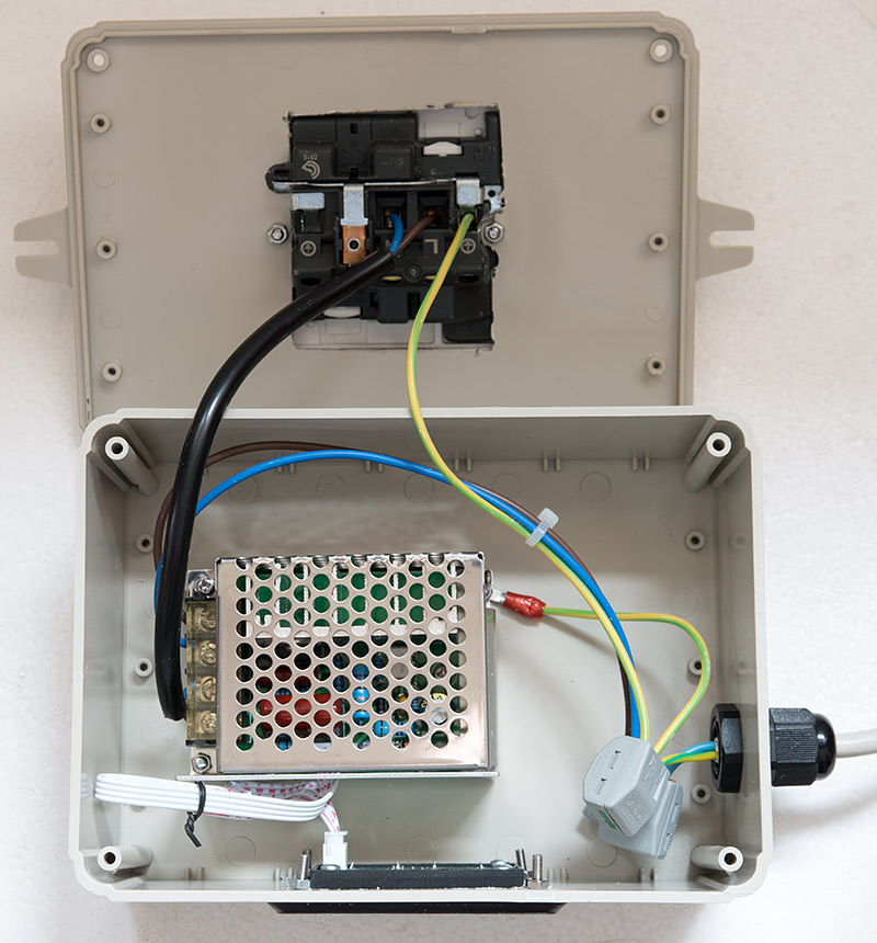
Work out how much wire you need to get from the controller to the socket and cut a length from your kettle lead. Leave enough length so that you can open the lid to service the unit. Strip and bare the live and neutral wires. Draw out the earth wire from the cable insulation using a pair of pliers. This neutered cable is the black one in the photograph.
Work out how much wire you need to get from your cable gland to the terminals on the controller. Cut this length from your kettle lead and draw out the individual 3 wires using a pair of pliers.
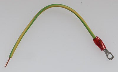
Bare each end of the earth wire that you drew out from the cable insulation. Crimp down your ring connector on to one end.

Slide the cable gland on to the kettle lead so all the fastenings are where they will need to be but don't tighten it yet.
Attach your three chocolate block mains connectors to the end of the kettle lead.
Make the following wire connections:
Incoming mains lead earth to socket earth.
Incoming mains lead live to controller terminal 1.
Incoming mains lead neutral to controller terminal 2.
Controller terminal 3 to socket neutral.
Controller terminal 4 to socket live.
Note that the legend on the controller heatsink indicates a different connection scheme that would result in the live cables being commoned together and neutral being the controlled line. This is not the usual pattern in the UK - ignore it. On the controller terminals 2 and 3 are commoned together. Terminal 1 is connected to the triac MT1 and terminal 4 is connected to MT2.


Step 5: Screw it together
Remove all the translucent blue protective plastic film that covers the unit.
Remove the metal shield from the triac controller by unscrewing the two screws that hold it in place and sliding it to the side to unhitch it from its tabs.
Fix the controller to the base using 2 M3 screws and nuts with the screw heads on the outside of the case. You'll probably need to use needle-nose pliers to hold the nut in place while you turn the screw into it.
Attach the ring connector on your loose earth wire to one of the screws so that it's held in place by your nut. Attach the other end of the earth wire to the incoming earth connector. Ideally you'd use a nyloc nut for this connection or apply a gob of hot glue to seal the thread from coming loose. It's up to you.
Reattach the metal shield to the triac unit.
Step 6: Safety testing
Set your multimeter to "continuity test" and touch the probes together to make sure it beeps. Hold one end of the probe against the earth pin of your mains power plug and check that you get a beep when you touch the other probe to the controller shield, the exposed screw heads on the base of the case, the earth plug hole on your 1-gang socket and the two screws on the face of the socket. If any of these fail then go back and check your wiring.
Step 7: Final assembly
Fix the display to the side of the case using four M3 screws and nuts.
Tighten up the cable gland using its backnut and then fully tighten the large outside part that grips the cable. The mains cable should not budge if you pull on it.
Fit the lid on the box being mindful of where you are pressing cables down. Try to avoid pressing them on to the area where the heatsink is located. Use cable ties if necessary.
Step 8: Testing
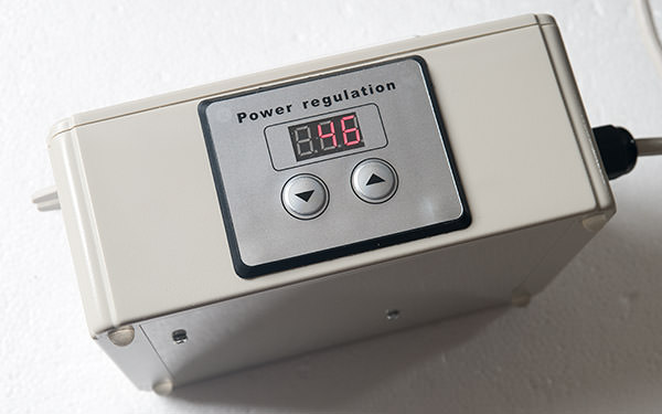
Find a table lamp with an incandescent bulb and connect it to the socket on the box. Do not use a CFL or LED lamp. Plug your trailing mains plug into a wall socket. The display should light up with some random percentage display. Check that your table lamp varies in intensity as you use the up/down controls on the digital controller.
If it all works as expected then you can stick on the front panel cover that will hide the buttons and screws.
You're done! Congratulate yourself on a job well done and have fun with your new power regulator.
Note: the control box is not IP rated so don't put it anywhere where it's going to get splashed. I keep mine next to the wall socket, well away from the boiler.

Using it on a brewday
I was slightly nervous about the lack of ventilation holes or any fan cooling for the triac heatsink so I thought I'd see how hot it got at 100% power while heating up my mash water. After about 20 minutes it was starting to get uncomfortably hot around the socket so I chickened out and connected the boiler directly to a wall socket. 100% power is not the intended use for this controller anyway.
Fast-forward and now I'm starting my boil. The boiler is plugged into the wall socket and a rolling boil has just started. I removed the plug from the wall and connected it to the regulator box. At 100% power my element was drawing 2200W. At 70% it was 1860W and at 60% it was 1500W. I settled at 60% as I was getting a nice gentle rolling boil.

At 60% there was no noticeable heat buildup around the unit. At the end of the brewday I still got a healthy 3.5 litre boiloff, used less electricity, ended up with about 1 litre more into the fermenter than usual and my predicted gravity was spot on. I'll certainly be using this on every brewday from now on.
Happy brewdays!
- Andy
This digital power regulator is the high power equivalent of a dimmer switch for a light. It regulates the current delivered to your heating element by performing phase-angle control on the mains sine wave. By regulating the intensity of your boil you can control your losses through boil-off, save money on the electricity needed and ultimately produce more beer from your brewday.
To build my power regulator I will use this module from ebay:
The listing states that it can control up to 4kW but only 2kW is recommended for long term use. I took it apart to find out the limiting factors.
The phase-angle control is performed using a triac, in this case the BTA41600B from ST Micro. This is quite a substantial triac that can handle up to 41A of continuous current at up to 600V. In practice you are limited by how well you can cool the triac and in this unit it is screwed to a decent looking aluminium heatsink using thermal transfer compound.
The worst case thermal scenario for a triac is when it's held fully on. The BTA41600B has a maximum on-state resistance of 10mOhm which at 2kW/240V load will result in a power dissipation from the triac of 7W (see AN2703). That doesn't sound like a lot but it's easily enough to destroy the triac if no heatsinking was provided.
In operation the circuit works like this. We start with the triac off and no current flows. The mains sine wave drops through zero on the X axis and a detection circuit on this board sends a pulse to a cheap Atmel 8-bit microcontroller housed on the external display board. The micro starts a timer with a duration inversely proportional to the selected power percentage. When the timer expires the micro sends a current pulse of sufficient magnitude to turn on the triac and of sufficient length to cause the triac to latch on. Power is now being delivered to your heating element. At the next zero-crossing the triac automatically switches off, the detection circuit sends another pulse to the micro and the sequence starts again. This is all happening 100 times per second.
Now you know how it works, here's how to build one.
Parts required
The controller pictured above from ebay. It should cost less than a fiver from China. Search ebay for "4kW power regulator"
A suitable box that is going to protect you from sticking your fingers where they don't belong. Mine is 170x125x70mm (L/W/D) and I reckon it's about the perfect size. You can buy them on ebay or you may already have something suitable at home. This box will house dangerous mains voltages so don't be tempted to go for a flimsy solution.
A 1-gang wall socket (available everywhere).
A cable gland (ebay search "cable gland").
A length of 3-core mains cable rated for at least 10A with a wall plug on the end. A donor 'kettle lead' is ideal if you chop off the IEC connector leaving a length of wire with a mains plug on it.
3 cable connectors, e.g. chocolate blocks or similar. The connectors I've used are available on ebay. Search "3 way cable connector".
8 M3 screws of about 15mm with nuts.
1 Ring-type wire crimp connector for M3 screws.
Tools required
Oscillating multi-tool or other means of cutting large openings in plastic
Hand file
Drill
Screwdriver
Needle nose pliers (optional)
Multimeter (optional)
Step 1: Cut an opening for the socket.
The wall socket will be positioned on the lid of the box. Offer it up to the lid and mark where the first screw hole will be. Drill a hole for the screw. Now mark where the other screw will be and drill that.
Now the hard part. Work out how much you need to cut away to make the socket fit flush with the lid. You will probably have to come quite close to the screw holes. Take care to ensure that you don't come so close that the plastic cracks. Use your multi-tool to do the bulk of the cutting and finish off with a file.
The screws supplied with the socket will probably be too long and in any case won't have nuts so use two of your M3 screws and nuts to secure the socket to the lid.
Step 2: Planning component locations
Work out where the controller will sit and where the mains entry hole will be. I left some space on the heatsink side of the controller in case I needed to come back later and fit a cooling fan.
Step 3: Cut the remaining openings
The controller has space for two screws to be fitted to hold it to the base. Mark where they will be and drill holes for them.
Drill a large hole for the cable gland. If you don't have a hole-saw bit then use the biggest normal bit that you have and use a round file to enlarge it to the size you need. Go steady with the file, it's all too easy to end up with an oval shape that doesn't get completely covered by the gland.
Work out where you want the digital display to be then mark and drill the four holes that it requires. Now cut the opening using your multi-tool and a file to finish the job.
Step 4: Wiring
Work out how much wire you need to get from the controller to the socket and cut a length from your kettle lead. Leave enough length so that you can open the lid to service the unit. Strip and bare the live and neutral wires. Draw out the earth wire from the cable insulation using a pair of pliers. This neutered cable is the black one in the photograph.
Work out how much wire you need to get from your cable gland to the terminals on the controller. Cut this length from your kettle lead and draw out the individual 3 wires using a pair of pliers.
Bare each end of the earth wire that you drew out from the cable insulation. Crimp down your ring connector on to one end.
Slide the cable gland on to the kettle lead so all the fastenings are where they will need to be but don't tighten it yet.
Attach your three chocolate block mains connectors to the end of the kettle lead.
Make the following wire connections:
Incoming mains lead earth to socket earth.
Incoming mains lead live to controller terminal 1.
Incoming mains lead neutral to controller terminal 2.
Controller terminal 3 to socket neutral.
Controller terminal 4 to socket live.
Note that the legend on the controller heatsink indicates a different connection scheme that would result in the live cables being commoned together and neutral being the controlled line. This is not the usual pattern in the UK - ignore it. On the controller terminals 2 and 3 are commoned together. Terminal 1 is connected to the triac MT1 and terminal 4 is connected to MT2.
Step 5: Screw it together
Remove all the translucent blue protective plastic film that covers the unit.
Remove the metal shield from the triac controller by unscrewing the two screws that hold it in place and sliding it to the side to unhitch it from its tabs.
Fix the controller to the base using 2 M3 screws and nuts with the screw heads on the outside of the case. You'll probably need to use needle-nose pliers to hold the nut in place while you turn the screw into it.
Attach the ring connector on your loose earth wire to one of the screws so that it's held in place by your nut. Attach the other end of the earth wire to the incoming earth connector. Ideally you'd use a nyloc nut for this connection or apply a gob of hot glue to seal the thread from coming loose. It's up to you.
Reattach the metal shield to the triac unit.
Step 6: Safety testing
Set your multimeter to "continuity test" and touch the probes together to make sure it beeps. Hold one end of the probe against the earth pin of your mains power plug and check that you get a beep when you touch the other probe to the controller shield, the exposed screw heads on the base of the case, the earth plug hole on your 1-gang socket and the two screws on the face of the socket. If any of these fail then go back and check your wiring.
Step 7: Final assembly
Fix the display to the side of the case using four M3 screws and nuts.
Tighten up the cable gland using its backnut and then fully tighten the large outside part that grips the cable. The mains cable should not budge if you pull on it.
Fit the lid on the box being mindful of where you are pressing cables down. Try to avoid pressing them on to the area where the heatsink is located. Use cable ties if necessary.
Step 8: Testing
Find a table lamp with an incandescent bulb and connect it to the socket on the box. Do not use a CFL or LED lamp. Plug your trailing mains plug into a wall socket. The display should light up with some random percentage display. Check that your table lamp varies in intensity as you use the up/down controls on the digital controller.
If it all works as expected then you can stick on the front panel cover that will hide the buttons and screws.
You're done! Congratulate yourself on a job well done and have fun with your new power regulator.
Note: the control box is not IP rated so don't put it anywhere where it's going to get splashed. I keep mine next to the wall socket, well away from the boiler.
Using it on a brewday
I was slightly nervous about the lack of ventilation holes or any fan cooling for the triac heatsink so I thought I'd see how hot it got at 100% power while heating up my mash water. After about 20 minutes it was starting to get uncomfortably hot around the socket so I chickened out and connected the boiler directly to a wall socket. 100% power is not the intended use for this controller anyway.
Fast-forward and now I'm starting my boil. The boiler is plugged into the wall socket and a rolling boil has just started. I removed the plug from the wall and connected it to the regulator box. At 100% power my element was drawing 2200W. At 70% it was 1860W and at 60% it was 1500W. I settled at 60% as I was getting a nice gentle rolling boil.
At 60% there was no noticeable heat buildup around the unit. At the end of the brewday I still got a healthy 3.5 litre boiloff, used less electricity, ended up with about 1 litre more into the fermenter than usual and my predicted gravity was spot on. I'll certainly be using this on every brewday from now on.
Happy brewdays!
- Andy