


C
cnelsonplumber
Guest
Just been dabbling around with the brewery and and made a flow measuring device out of a few copper fittings and a bit clear tube thought I would share.
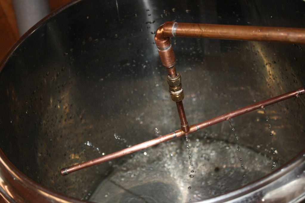
The basic idea is a simple manometer connected to the sparge line so that I can monitor the sparge rate without taking the lid off the Mash tun.
I borrowed this idea from Bernoulli who was a mathematician in the 1700s. :thumb: Basically he said that "In fluid dynamics, for an inviscid flow, an increase in the speed of the fluid occurs simultaneously with a decrease in pressure or a decrease in the fluid's potential energy."
What that means is that if you reduce the diameter of a pipe, for example through a nozzle, a change of pressure can be recorded corresponding to the pressure and hence flow. He actually says lots more but lets not get bogged down in fluid thermodynamics :nono:
The easiest way to build a DIY nozzle is with a few copper fittings these are 15mm and 8mm
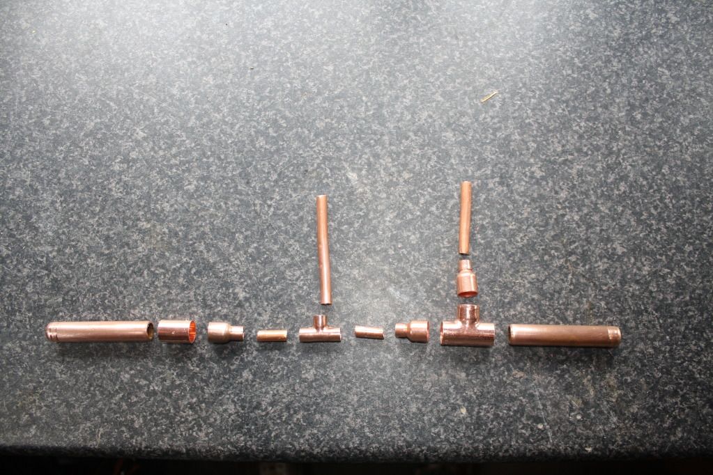
Solder them together.
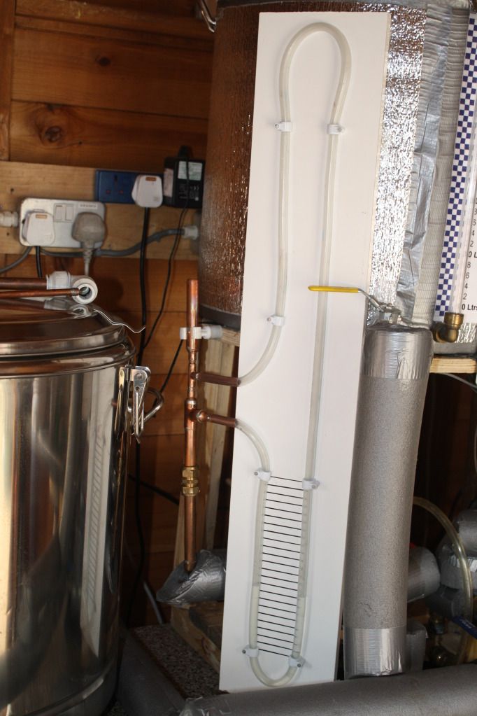
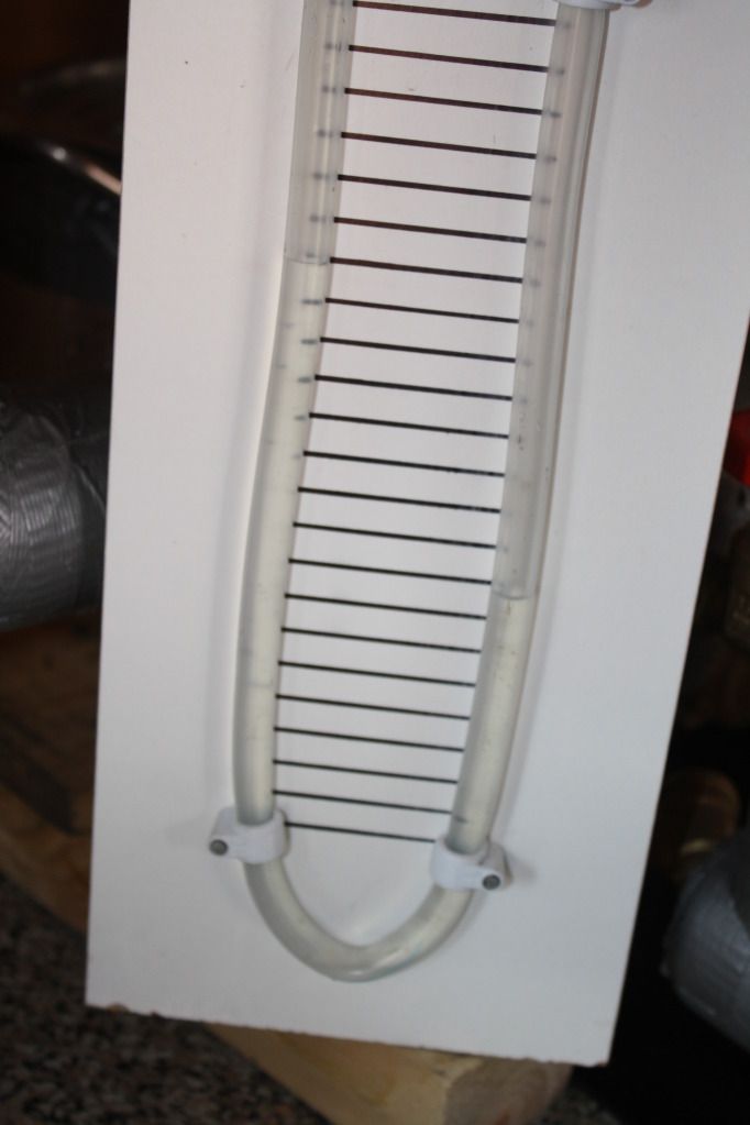
and there you have a home made nozzle with tubes for the manometer, which looks like this when you put it together:
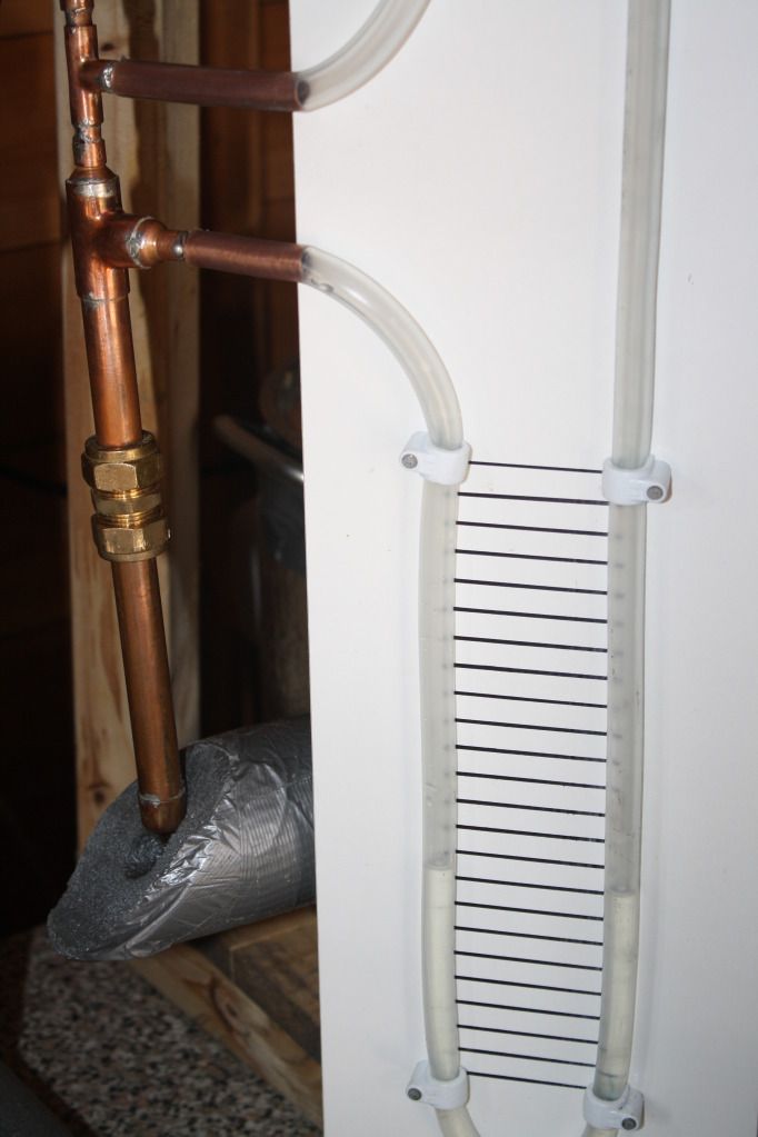
The tube is extended vertically so that the pump doesn't simply fill your manometer tube up.
The scale is horizontal lines 1cm part used for reference only.
All you need now is a measuring jug and a watch with a second hand. Simply set the pump flow rate using whatever control you have, (I use a bypass valve and speed controller) and note the difference in the manometer levels in cm then measure the flow into a jug over 1 minute.
Repeat this for various flow rates and plot a graph if you like. I have just made a note on the side of the manometer.
My sparge arm stalls at around 0.85 litres/min due to friction in the make shiftbearing but that is low enough to satisfy the rate I am looking for.
The basic idea is a simple manometer connected to the sparge line so that I can monitor the sparge rate without taking the lid off the Mash tun.
I borrowed this idea from Bernoulli who was a mathematician in the 1700s. :thumb: Basically he said that "In fluid dynamics, for an inviscid flow, an increase in the speed of the fluid occurs simultaneously with a decrease in pressure or a decrease in the fluid's potential energy."
What that means is that if you reduce the diameter of a pipe, for example through a nozzle, a change of pressure can be recorded corresponding to the pressure and hence flow. He actually says lots more but lets not get bogged down in fluid thermodynamics :nono:
The easiest way to build a DIY nozzle is with a few copper fittings these are 15mm and 8mm
Solder them together.
and there you have a home made nozzle with tubes for the manometer, which looks like this when you put it together:
The tube is extended vertically so that the pump doesn't simply fill your manometer tube up.
The scale is horizontal lines 1cm part used for reference only.
All you need now is a measuring jug and a watch with a second hand. Simply set the pump flow rate using whatever control you have, (I use a bypass valve and speed controller) and note the difference in the manometer levels in cm then measure the flow into a jug over 1 minute.
Repeat this for various flow rates and plot a graph if you like. I have just made a note on the side of the manometer.
My sparge arm stalls at around 0.85 litres/min due to friction in the make shiftbearing but that is low enough to satisfy the rate I am looking for.
 I think the flow meter route is the way to go, although I am not sure I have the measure of the Arduino. Is anyone using the arrangement? :thumb: