Smileyr8
Impressive Member
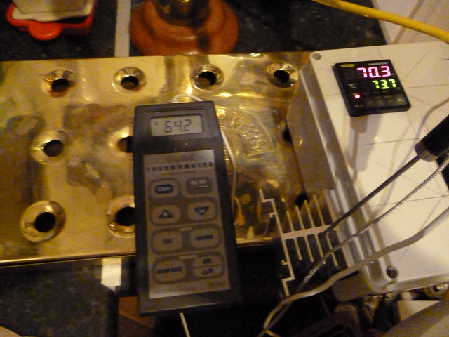
MyPIN PID ordered and a solar pump, I plan to use the solar pump to draw wort from the area at the bottom of the boiler where the element sits and return it to the top of the boiler throughout the mash process circulating the wort, I will sit the PT100 sensor in the return pipe thus ensuring constant flow over the grain and temperatures hopefully maintained better throughout. I don't have everything laid out as yet but once it's in place I will post some pictures.
 ).
).