


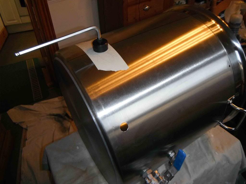
The sight glass, recirculation ball valve, output ball valve and heating element are identical to, and are mounted in exactly the same way as, the fittings on my HLT described in earlier posts (viewtopic.php?f=13&t=48378 and viewtopic.php?f=13&t=48416). So I will not dwell on any more detail here. Unlike the HLT, a temperature probe âTâ piece on the output valve is not necessary on the boil kettle as the output will be going straight into the wort chiller. None the less, measurement of the temperature in the boil kettle is still required to be fed back into the respective PID in the control panel, so a 4â PT100 probe is mounted horizontally into the sight glass bottom T. When I previously described the HLT build I did not give much information on how the 5500kW element was fitted, so I will first spend a little time on this. In fitting the elements I have used USA electrical parts as they seem better suited to a high-current electric home brewery. The element head and wiring connections are mounted in a weatherproof two gang conduit box purchased from here: http://www.tizaro.com/product/EL1K5B. On the back of the cast aluminium conduit box I drilled a 2.25â hole with a Starrett. Across the back of the box I bolted a square 1mm thick stainless steel plate, the dimensions of which all-round are 3/8â smaller than the box. In the exact middle of this plate I used a 1.25â Q-Max to make a hole concentric with the 2.25â hole in the box. I mounted the plate with stainless steel bolts of the countersunk type to ensure the exterior surface of the plate was flush. Before fitting the bolts and mounting the plate on the box I used JB Weld to make it watertight around the bolts, central hole and plate edges. The Q-Max 1.25â punch was also used to make a hole in the kettle for the element to pass through. The hole on the boil kettle is at 4-1/8â centre from the outside bottom of the pot. This is one inch higher than I mounted the element on the HLT â it needs to be slightly higher to clear the hop stopper described in Part 6a.
To make the weldless fixing of the element I used a high temperature silicon âOâ ring (http://www.amazon.com/gp/product/B000FM ... UTF8&psc=1) and a stainless steel shim (http://www.amazon.com/gp/product/B006U2 ... UTF8&psc=1). Pictures below show the element components before and after the mounting:
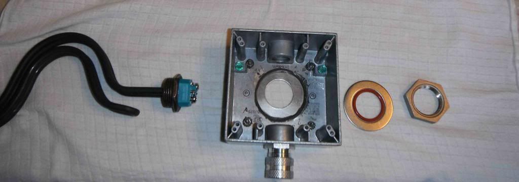
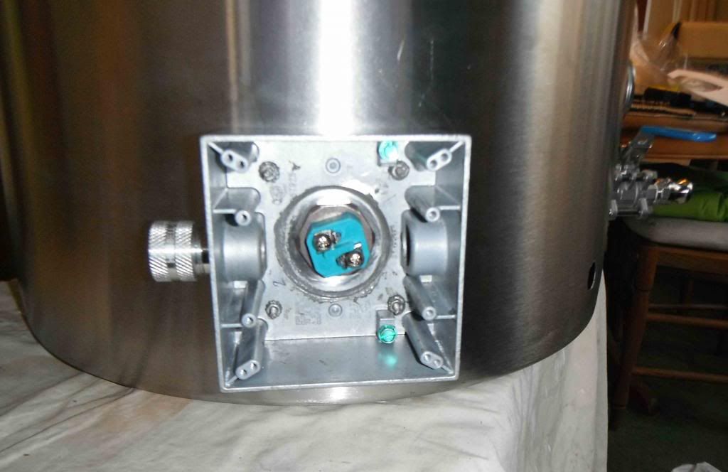
To mount the element you pass it through the hole in the plate at the back of the conduit box and then through the hole in the pot, via the silicone âOâ ring and retaining shim. A 1â BSP/NPT stainless steel nut (http://www.amazon.com/gp/product/B003GX ... UTF8&psc=1) is screwed down as hard as you can on the element thread inside the pot. No washer is necessary under the nut.
You may wonder why I fixed a stainless steel plate on the back of the conduit box, rather than simply mount the box itself against the pot wall using the âOâ ring and shim. This is because the cast aluminium is very brittle and the box would most certainly crack under the tightening pressure of the element mounting nut.
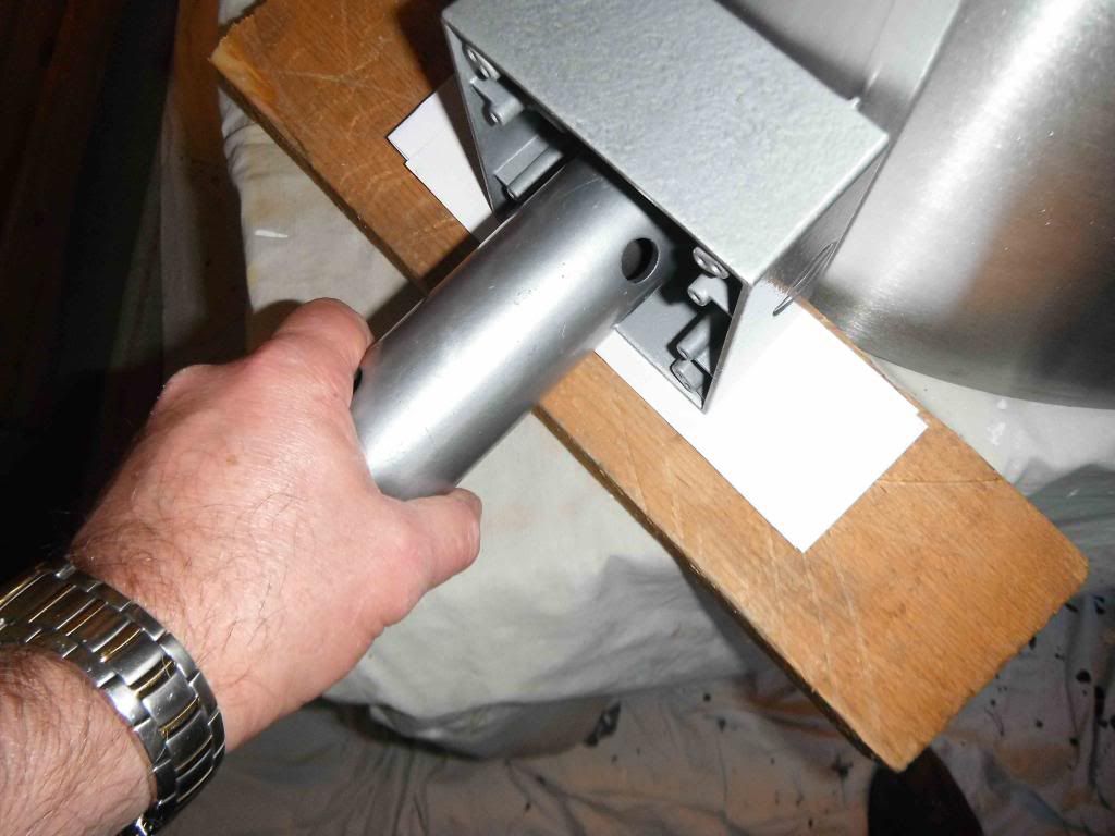
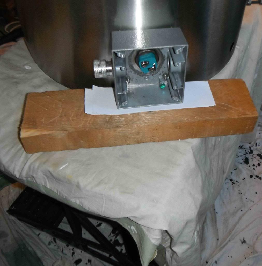
The element and the conduit box have a strong tendency to twist as you tighten the element nut. To keep everything square and prevent this a 1.5â AF box spanner is placed over the element head in the conduit box and a block of wood of appropriate height is placed under the conduit box itself while tightening the nut â see pictures below:
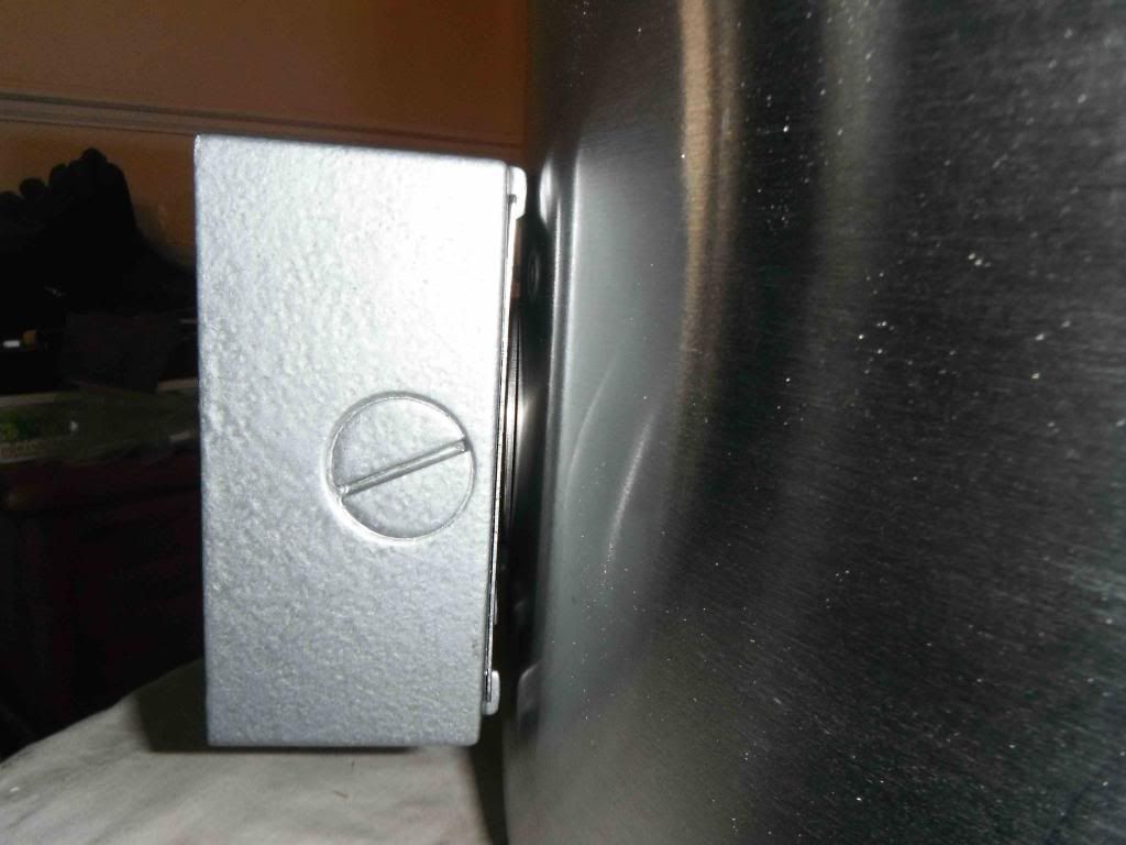
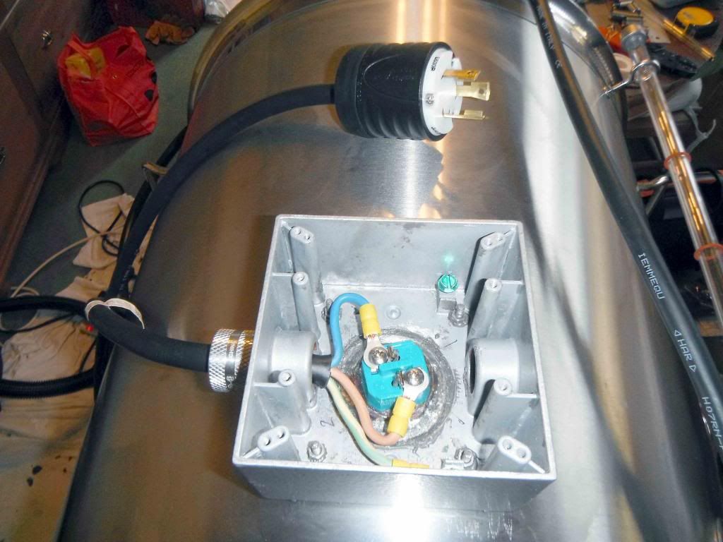
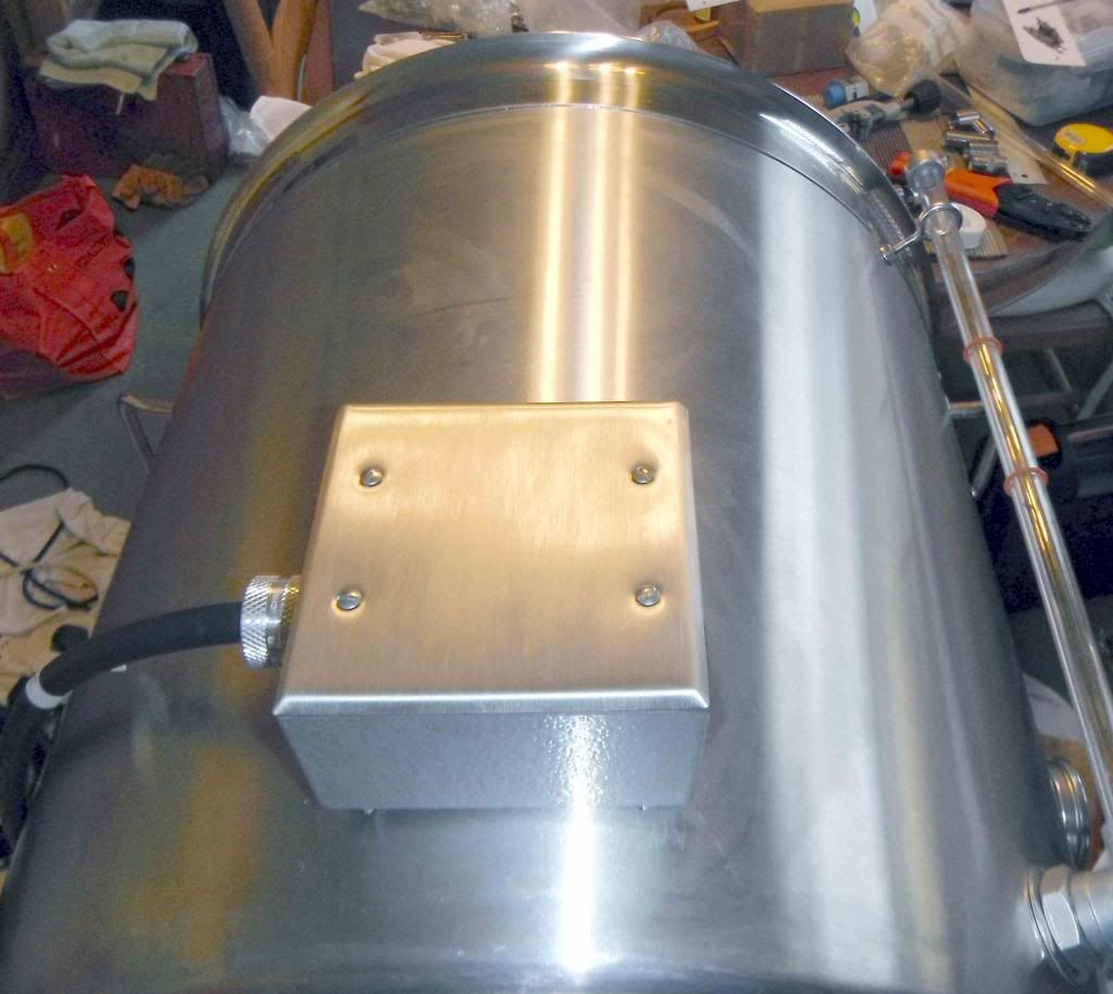
After testing for leaks, a bead of transparent silicone sealant can be gunned around the element head in the conduit box as an extra precaution. The conduit box as supplied is a dull grey. I sprayed hammered silver paint on the box to give it a more attractive look. To close the front of the conduit box I bought a brushed-finish stainless steel cover (http://www.amazon.com/gp/product/B0002B ... UTF8&psc=1). The conduit box is supplied with a black foam waterproof seal and this is placed under the cover before screwing the cover in place. The 30A power cable is taken out of the box through an aluminium waterproof gland (http://www.tizaro.com/product/EL4622/hu ... 25-conduit). I put some silicon sealant on the threads of the gland before screwing it into the conduit box. Also make sure that you get blanking plugs to close off any unwanted holes in the box (http://www.tizaro.com/product/EL1JKH/be ... proof-gray). The element power cable is terminated in a NEMA L6-30 male plug which connects into the appropriate control panel receptacle. Here are some more pictures of the element conduit box:
Which side of the pot you fix the element is not critical. I placed the HLT element on the right of the pot and the boil kettle element is on the left. This means in my case that both conduit boxes can stick out over the edge of the brew stand and not bash into other pots on the stand.
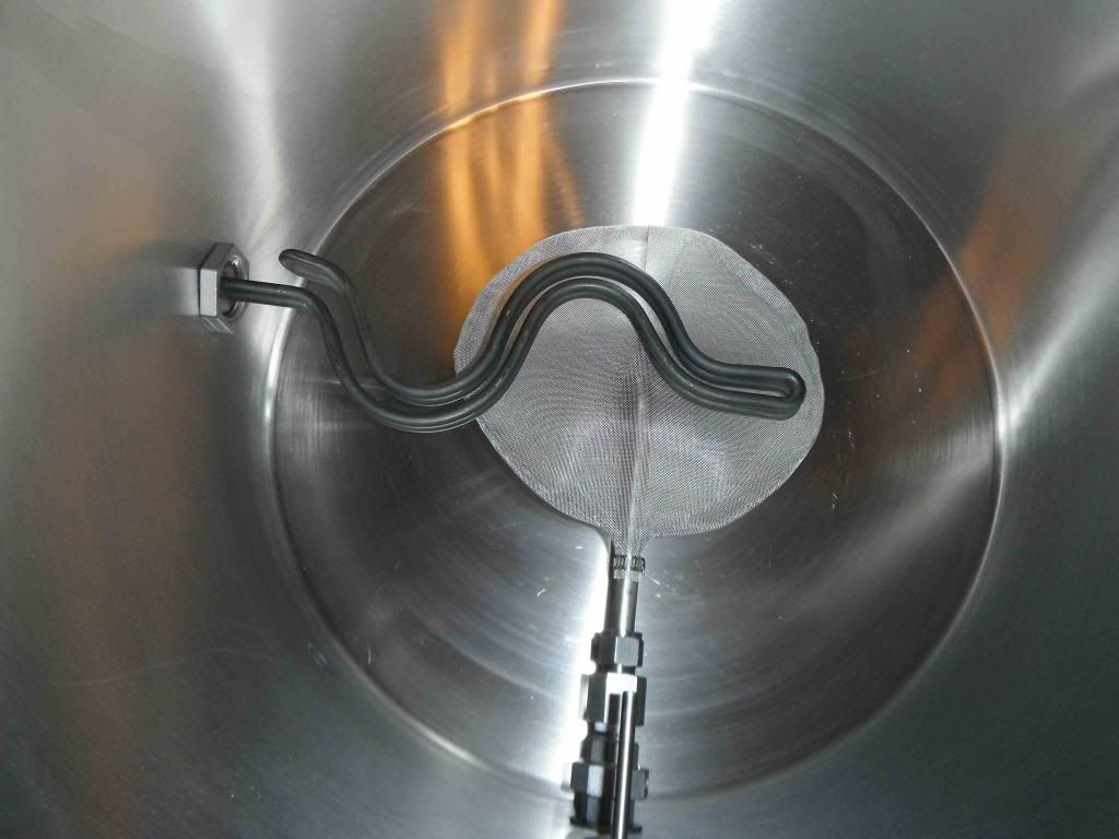
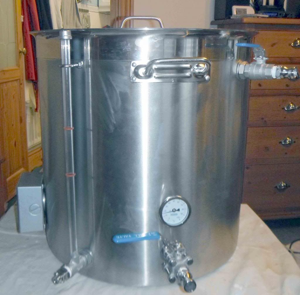
You will note that I have fitted a recirculation ball valve to the pot. This is not really necessary on a boil kettle as the hose from the mash tun when sparging (via the wort pump) could simply dangle over the side of the pot. However, in the stress of brewing I tend to be a trifle clumsy at times and make silly mistakes. What concerned me was that I might accidentally pull on the connecting hose and lose all that lovely wort on the floor. A firm connection with a camlock and ball valve seemed preferable to me! Besides which, the ball valve gives me the opportunity to experiment with a recirculating hop boil as some brewers advocate. If I try this though I would need to replace my hop stopper with a different type of hop filter â the makers of the particular hop stopper I purchased advise that it is not suitable for recirculating the wort in the kettle as this will compact the hops onto the screen and clog it.
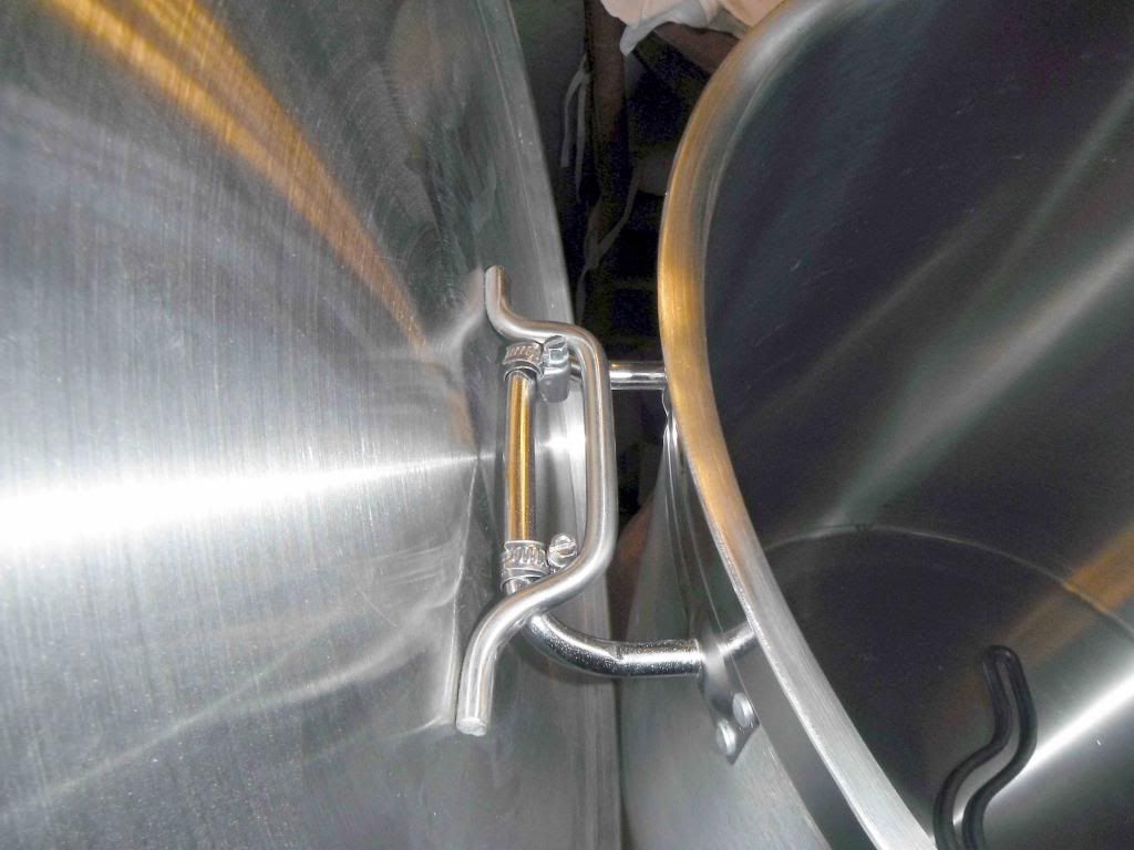
One last thing I did to the boil kettle (and the HLT) was to fit two stainless steel jubilee clips size 8-12mm to the rear handle. The lids on these pots are pretty big and the question arises what do you do with the lid when you take it off the pot to add something? They are really too large to fit on a table, you donât want to put them on the floor, and if you drop one it could guillotine your toes! So, the jubilee clips allow me to hang the lid on the back of the pot safely out of the way, as shown below:
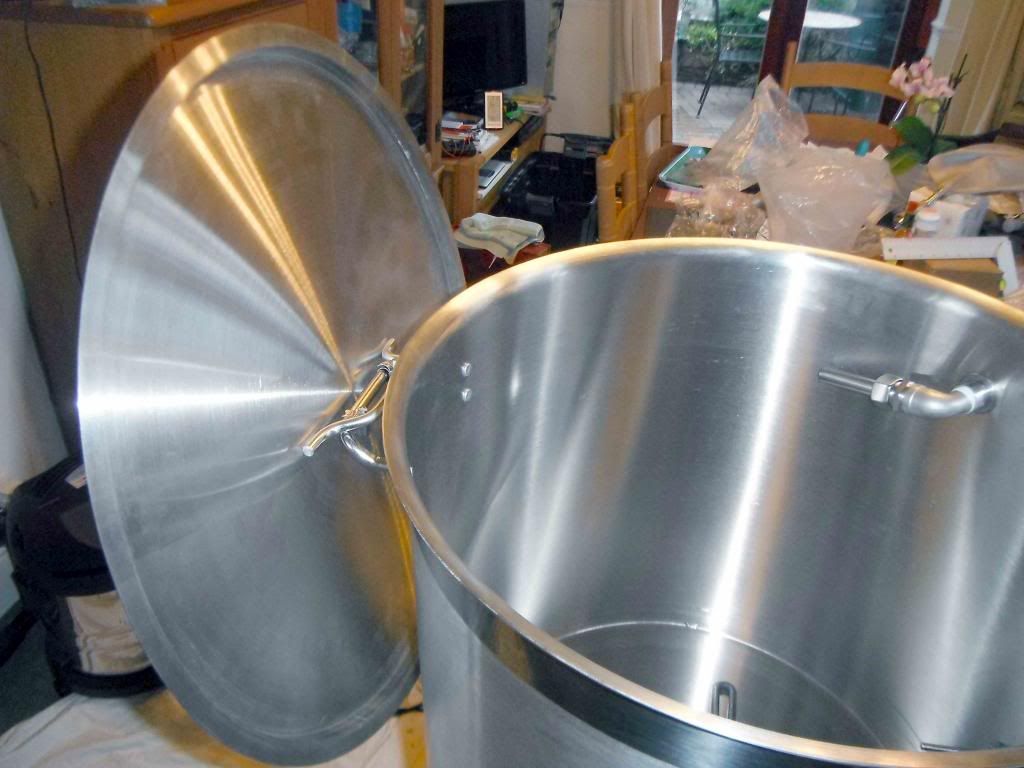
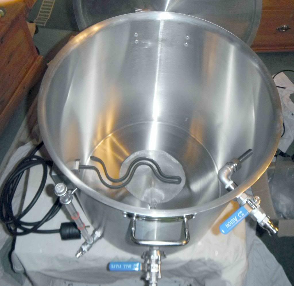
Final pictures show views of the inside and outside of the boil kettle, with only the sight glass left to be calibrated.
Well thatâs the boil kettle out of the way. My next posts on My Electric Brewery construction will detail the more mundane ancillary equipment, such as the brew stand, that will be necessary to get my new brewery up and running.
To make the weldless fixing of the element I used a high temperature silicon âOâ ring (http://www.amazon.com/gp/product/B000FM ... UTF8&psc=1) and a stainless steel shim (http://www.amazon.com/gp/product/B006U2 ... UTF8&psc=1). Pictures below show the element components before and after the mounting:
To mount the element you pass it through the hole in the plate at the back of the conduit box and then through the hole in the pot, via the silicone âOâ ring and retaining shim. A 1â BSP/NPT stainless steel nut (http://www.amazon.com/gp/product/B003GX ... UTF8&psc=1) is screwed down as hard as you can on the element thread inside the pot. No washer is necessary under the nut.
You may wonder why I fixed a stainless steel plate on the back of the conduit box, rather than simply mount the box itself against the pot wall using the âOâ ring and shim. This is because the cast aluminium is very brittle and the box would most certainly crack under the tightening pressure of the element mounting nut.
The element and the conduit box have a strong tendency to twist as you tighten the element nut. To keep everything square and prevent this a 1.5â AF box spanner is placed over the element head in the conduit box and a block of wood of appropriate height is placed under the conduit box itself while tightening the nut â see pictures below:
After testing for leaks, a bead of transparent silicone sealant can be gunned around the element head in the conduit box as an extra precaution. The conduit box as supplied is a dull grey. I sprayed hammered silver paint on the box to give it a more attractive look. To close the front of the conduit box I bought a brushed-finish stainless steel cover (http://www.amazon.com/gp/product/B0002B ... UTF8&psc=1). The conduit box is supplied with a black foam waterproof seal and this is placed under the cover before screwing the cover in place. The 30A power cable is taken out of the box through an aluminium waterproof gland (http://www.tizaro.com/product/EL4622/hu ... 25-conduit). I put some silicon sealant on the threads of the gland before screwing it into the conduit box. Also make sure that you get blanking plugs to close off any unwanted holes in the box (http://www.tizaro.com/product/EL1JKH/be ... proof-gray). The element power cable is terminated in a NEMA L6-30 male plug which connects into the appropriate control panel receptacle. Here are some more pictures of the element conduit box:
Which side of the pot you fix the element is not critical. I placed the HLT element on the right of the pot and the boil kettle element is on the left. This means in my case that both conduit boxes can stick out over the edge of the brew stand and not bash into other pots on the stand.
You will note that I have fitted a recirculation ball valve to the pot. This is not really necessary on a boil kettle as the hose from the mash tun when sparging (via the wort pump) could simply dangle over the side of the pot. However, in the stress of brewing I tend to be a trifle clumsy at times and make silly mistakes. What concerned me was that I might accidentally pull on the connecting hose and lose all that lovely wort on the floor. A firm connection with a camlock and ball valve seemed preferable to me! Besides which, the ball valve gives me the opportunity to experiment with a recirculating hop boil as some brewers advocate. If I try this though I would need to replace my hop stopper with a different type of hop filter â the makers of the particular hop stopper I purchased advise that it is not suitable for recirculating the wort in the kettle as this will compact the hops onto the screen and clog it.
One last thing I did to the boil kettle (and the HLT) was to fit two stainless steel jubilee clips size 8-12mm to the rear handle. The lids on these pots are pretty big and the question arises what do you do with the lid when you take it off the pot to add something? They are really too large to fit on a table, you donât want to put them on the floor, and if you drop one it could guillotine your toes! So, the jubilee clips allow me to hang the lid on the back of the pot safely out of the way, as shown below:
Final pictures show views of the inside and outside of the boil kettle, with only the sight glass left to be calibrated.
Well thatâs the boil kettle out of the way. My next posts on My Electric Brewery construction will detail the more mundane ancillary equipment, such as the brew stand, that will be necessary to get my new brewery up and running.
Last edited by a moderator:
