converting a milk pasteuriser to RIMS-

The Homebrew Forum

Help Support The Homebrew Forum:

This site may earn a commission from merchant affiliate links, including eBay, Amazon, and others.

Talon_Ted

Active Member
Joined
May 14, 2010
Messages
78
Reaction score
0
i have been thinking about building a RIMS for sometime amd have decided to get on with it.

about 10 years ago i bought a second hand milk pasteuriser for a project which never got off the ground. it seemed sensible to have a look at the parts, some of which i have robbed over the years, to see if anything was usable.

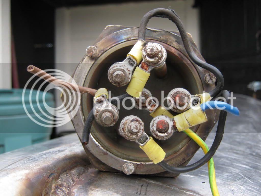
looking at it now the pasteuriser appears to work on the HERMs principle rather than the RIMs but i am hoping that i can convert it. there is avery nice heavy duty ss tube which houses 3 heating elements which i think total 9kw and are 3ph. my plan is to replace them with a low density heating element, though i am struggling to find one at the moment. the process controller box contains a gulton west 3300 which i hope is a pid of some sort and various relays. there is a basic thermostat for the tube and 2 more advanced probes in the pipe lines, one of which broke on removal. there is also a lead to a pump, heater and a 3 way valve.

i am hopeful that i can use the ss heavy duty tube, although it rather larger than i need being approx 600mm long. but i am not sure whether the controllers will be any use. can anyone advise me please? i will try to put som photos up if anyone is interested.

thanks

mark
 
Controller: http://www.westmexico.com.mx/pfd/west/m ... Manual.pdf
So it is a PID. (I notice it has a lithium battery - this will almost definitely need replacing.)

Heaters: 9KW 3 phase - but what voltage? Wired in star or delta? center neutral or no neutral connection?
If 415V, each element could be 3KW at 240V.
Consider using two or three in series at 240V for low density.

Just a couple of ideas - be confident before you start experimenting with this sort of gear - check all earthing etc!
 
drut

thanks for the info. unfortunately i have given the element assembly a bit of a bashing getting in out of the ss tube, however the elements and connectors are ok. but i cut the casing off with an angle grinder!

what i don't know is how you convert these apparently standard elements for heating water to low density ones heating wort? is that what you are saying might be possible depending on voltage?

mark
 
If the supply voltage was 415V 3 phase, the line to neutral voltage will be 240V.
If you have elements which are connected without a star centre point, the elements are designed for 415V.
If you have a star point, isolated or not, the elements are designed for 240V.

So, with a star point system:
If you connect either two in series, three in series, or two in parallel and then one in series with that pair, you will have three choices of dissipation because you are dividing the 240V between the elements.
Each of the elements will be getting less hot, so it will be lower density heating.

3KW is far more than you need for a single RIMS/HERMS heater unless you are trying to heat the mash tun from scratch or ramping very fast. However, with a bit of thoughtful switching you could achieve both.

Non-star:
If the elements are delta connected, i.e. without a centre point, connecting them each to 240V will again result in much less heat being generated.

This is resonable if you want a bit of 3 phase theory:
http://en.wikipedia.org/wiki/Three-phase_electric_power
 
drut

IMG_0726.jpg


here is photo of the connections for the heating elements. what do you reckon?

i didn't realise the elements were that flexible that you could play with the voltage. do you think this would be possible in this situation? would it be simpler and cheaper than buyinga low density element?

mark
 
Looks to me like you've got an isolated star wiring plan, with brown, black and blue phases, black neutral and green/yellow earth. The neutrals from each element are connected to each other and nothing else, which is the black wire running round three terminals without an end coming out, the remaining black, brown and blue are the phase in's.

You should be able to run that on 240V single phase, running all three elements in series would give a total power somewhere in the region of 950W, pulling 4A. Two in series would give 1400W, and two in parallell followed by one in series to that pair would give 1900W. Designing a controller for that lot could be interesting, lots of SSR's involved!

Tim
 
timbim

thanks for the info. would running three in series outputting 950W be 'low density' enough to have direct in the wort?

thanks

mark
 
Speaking as one who suffered a simple 3kw element failure in my boiler yesterday whilst doing a small 23 litre brew, the hassle involved was solvable but not desirable. :evil:
Once you start to series up resistors, elements, the chances of a potential failure increases, especially with old elements, resulting in no heat, at best ;)
I am all in flavor of using what is to hand but could not help thinking if TTs kit is really suitable, having not seen it, cos if an element fails at some time, the kit will probably be extinct, leaving a brew wasted to boot. :evil: :evil:
Just my thinking.......... is the kit really adaptable and worth using or would a purpose build be better with a new 240 volt element :hmm:
Speaking also of one who has been somewhere like this before, with a 60 litre Bartlett stainless catering water heater / steam producer, still sitting in the workshop with 3 times 5 kw heaters. Proper 3 phase is to hand, but decided the kit was not worth using, for my purpose. ;)
 
Talon_Ted said:
thanks for the info. would running three in series outputting 950W be 'low density' enough to have direct in the wort?

The power dissipated by each element is 1/3 of the total, so not more than 320W per element. Haven't got a clue whether it's low enough density, compare the specs of a known good element and work it out from there.
 
Timbim is spot on with the wiring and plenty close enough with the sums.
I think I would go with two in series and leave the third as a spare - which ties up with Springer's idea of "extinct".

However, as you would be running the elements at 1/4 rated power, the chances of a failure would be greatly reduced.

What concerns me more is the discolouration at the top of your view, along with the melting on the top black and brown leads.
There is also some sign of possible over-heating on the ground crimp and the crimp which has the melted black wire - some of this could be due to your delicate removal operation... You should have the element checked out for resistance (nominally 19.2 ohms each) and for insulation before proceeding further.
 
And of course it goes without saying that you need to rewire the lot, I'd be tempted to get some high temperature rated cable to do it with, and the correct crimps.

Thinking back, doesn't the fact that we're talking peak voltage rather than RMS muck up the DC calculations? Not a great electrical engineer, give me a colony of Drosophila (or a decent yeast culture) any day!
 
We are talking RMS, nothing to do with peak or DC. An SSR passes the full waveform, it does not rectify.

As for the 415/240 bit, just consider your local electricity distribution. 415V is the phase-to-phase voltage. 415V 3 phase comes from the nearest major step-down transformer and an equal number of houses are connected to each phase - with neutral. (Protective Multiple Point Earthing (PME) should ensure that your neutral is very close to ground.) All get 240V (415 / square root of 3), but if you use power from your neighbour's garage it could be a different phase (then bang....)
 
I understand that an SSR is in effect no different from a standard switch (although radically different in mechanism).

My understanding of 415V 3 phase is that it is so called because that's the maximum phase-phase voltage.

My comment about RMS comes from the fact that I calculated the currents and resistances from an assumption of a 240V DC voltage, RMS voltage of a 240V sinusoid is more like 170V.

I'll assume I'm not quite thinking straight here, these multi-factor crosses are getting confusing!
 
Looks like you boys know your electrics ;) I can manage Ohm's law and resistors in parallel and series and a bit more, then I'm out :lol:
As was mentioned the elements will be under running their design, so might give a reliable service life, but would like a picture from TT to see if it worth adapting the kit, as I said. :) Thats not a decision for me, but would like to view a pasteuriser.
As I said not an electrical expert, but would a "normal" element controlled by a SSR not give the required effect. :?
 
Would be nice to see a picture of the inside, not just the slightly worrying electrics!

Replacing the elements would work, but if that works and doesn't leak, what's the point of pulling the thing apart and replacing working parts? Making work for yourself, as well as additional expense if you ask me. If it does work, that is.
 
timbim said:
I understand that an SSR is in effect no different from a standard switch (although radically different in mechanism).

My understanding of 415V 3 phase is that it is so called because that's the maximum phase-phase voltage.

My comment about RMS comes from the fact that I calculated the currents and resistances from an assumption of a 240V DC voltage, RMS voltage of a 240V sinusoid is more like 170V.

I'll assume I'm not quite thinking straight here, these multi-factor crosses are getting confusing!

Don't think of your heater elements as 3 phase, think of them as 3 seperate coils of wire wired to a 3 phase supply, they are no different to having three kettle elements wired in three phase, and will work on single phase with no issues, the reason they are wired in 3 phase is to balance the loading on the electical supply when running 3 elements, so one phase isn't doing more work than the other 2.

The quoted Mains voltages from the electric companies are RMS and all calcs should be based on 220/230V (usually 220v now) single phase european std now the allowed tolerances are 216.2v to 253V

Three phase 415 is now quoted as 400v I belive now, will have to dig my 17th ed regs out have not read them since i did the exam in 2009, (I have no real need for them as I don't (and never will) house bash).

I don't think there is a neutral on your heating element circuit above, just 3 phases and earth L1 L2 L3 and earth, each phase is 220v but the 415v is measured between phases, apart from that everything else in the advice you have had so far, appears to be in order, wire 2 elements in series and run it on 240V, keeping one spare.

Make sure you rewire it before testing and I would use high temp cable to do so. also make sure the elements are covered with a liquid before switching on or you will burn them out rapidly.

Also ensure everything is very well earthed!!!!!!!

If unsure get a qualified electrician to do it for you, or you may fry.

UP
 
+1 to the earthing point, my advice would be to get a multimeter with audible continuity test, clip one test lead to the earth lug on the wiring, and then go round the entire set up with the other lead, touching anything made of metal, making sure it beeps. If something doesn't, then you've got an earthing fault which needs sorting before you energise the thing. Once you've done that and got it rewired, please please use it connected to an 30mA RCD, so if there's any current leakage to earth it'll trip out straight away.

Sounds like you've got yourself a pretty fun project there anyway.

Tim
 
I really do not advise using an ordinary DVM with bleep! You need an earth bonding meter to be sure of the integrity.
This passes a significant current through the test piece.
If there is any corrosion in the connections, this will not show at the very low currents used by the average DVM.

For the insulation resistance test, a proper meter is also required. With these elements the test voltage should be 1KV.

Unclepumple is generally right but if you want the actual figures, chapter and verse:

Following voltage harmonization, electricity supplies within the European Union are now nominally 230 V +/- 10% at 50 Hz. For a transition period (1995-2008), counties that had previously used 220V changed to a narrower asymmetric tolerance range of 230V +6&% -10% and those (like the UK) that had previously used 240V changed to 230V +10% -6%.
(There is more to it but I can't copy and paste without getting a "General Error"!)
http://en.wikipedia.org/wiki/Mains_power - I quote this simply because it is easy to read!

So the nominal 3 phase mains voltage is indeed 400V (230 x sq rt of 3).

220V is relative to the older European 3 phase distribution standard of 380V.

Timbim - the peak mains voltage (crest of the sine wave, plus upper tolerance) for nominal 230V is 358V and the peak for nominally 400V phase-to-phase is 622V.

It can come as a surprise to students that the maximum peak-to-peak mains voltage is 716V - this is why semiconductors used at mains voltages are usually rated at 800V.
 
Drut - good points you make, I cede to those with a better knowledge and actual qualifications than me. Same for UP.

Given the test kit required to check it all out, probably easiest to get an electrician in to do the testing. Might be useful to get a 32A socket installed in your brewing area so you can run two elements in parallell rather than running feeds off separate final circuits around the place. Also useful if you ever want to get a decent welder going, with that much SS there's probably quite a lot you can do :hmm:
 

Latest posts

Back
Top