


After the failure of my attempt to build a RIMS with a towel rail heater (They are made of temperature self limiting thermoplastic), and the conversion of the under back to have a kettle element in it . . . which worked but was a bit harsh. I decided it was time to bite the bullet and build an inferior HERMS system :lol:.
Having Acquired the Bits
TODO: List and cost Bits and Suppliers
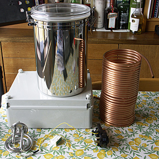
5L Stainless Storage Container - Woolworths - 5 quid (It was during the last days of the company)
Cheapy corded Kettle - 7.99 from Morrisons . . . I used this one as it had long pins on the element, unlike some of the cheaper cordless ones that only have short pins.
10mm 6mm dia copper tube - BES . . . Coiled round a 2L PET Bottle . . . It needs to be reduced in height to fit it in, but I can do that when I have the fittings I need . . . 6mm to 15mm are not easy to find.
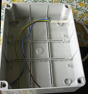
I thought that I had better put them all together . . . What I was after was a HERMS unit I could swap between the big and little brewery and make it 'self contained'. Using the IP56 box meant that all the electrics would be inside and not exposed . . . and as long as I seal all the holes with a suitable sealant it will retain the IP56 rating.
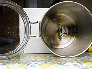
The first step was to decide on a position for the Heat Exchanger, and drill some holes for the studs that I was going to secure the Heat Exchanger to the lid of the box.

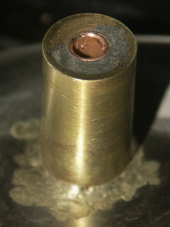
Turning the lid over and positioning it on the lid allowed me to mark the position of the holes on the Heat Exchanger, so I can drill them and braze in some studs.The studs are simply some 6mm stainless button headed bolts from aruncas that have been fitted through some very tight holes in the bottom of the storage container . . . I used a silver solder and flux from CuP Alloys.
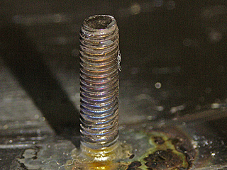
The potassium fluroborate flux needs to be molten to work and this happens at about 575C . . so you are well above solder temps and need to use a MAPP gas torch . . . but the solder melts at just above 600C anyway . . . these are fairly small components so it is pretty easy to braze . . . Thicker steel and larger brass components are much harder as the heat is just absorbed. . . . They take a bit of cleaning up too
Using a Kettle element nicked from a cheapo kettle mounted in the base of the storage container so that I don't have to worry about the curve of the pot . . . plus it keeps the exposed terminals inside away from any liquid.
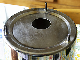
That's a 38mm hole, drilled with my new Bosch Cobalt Hole saws . . surprisingly easy, just take it slow and use a good cutting oil . . . with these very thin vessels it goes through easily . . . I would have preferred to use a QMax Punch but only had a 40mm which while usable was just too big to be reliable.
I also had to cut a suitable hole in the box lid to position the hole, that was fairly easy as it was just plastic and my big 64mm cheapo hole saw did the job.
You can also see that I have cut the holes for the PID Controller Auber Instruments and a Neon light to tell me when the element is 'on'. Despite me having the hole off centre (I have to make room for the outlet of the coil which will go into and out of the box), I managed to get the element pretty central in the storage container.
I suppose I should clean up the inside as well . . . when I dismantle it all to fit the coil is probably a good time. . . . Back to concentrating on the wiring . . .
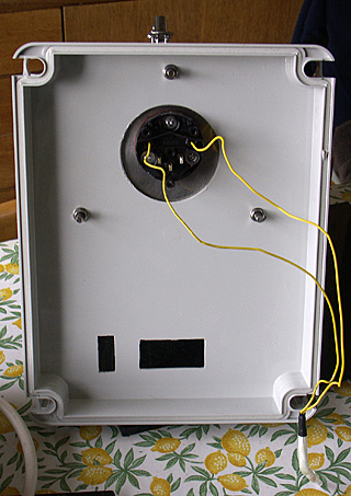
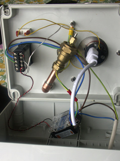
Decided to fix the supply using a cable gland rather than any sort of socket . . . this means I can plug it into any spare socket. I've fitted the PID and Neon in place. The neon gets its feed from the wires that were originally connected to the kettle element. The 25A SSR is hiding on the left side . . . I will be cutting a big hole there to mount a BMF heatsink (with More Sealant required . . . Still silicone is good to 475C anyway . . .
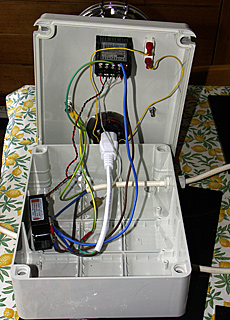
As you can see I used the original lead supplied with the kettle . . . waste not want not.
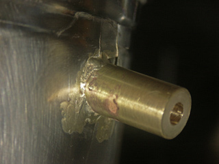
I had a mate machine me some trick fittings to allow me to go from the 6mm tube to 15mm compression plumbing fittings. Drilled a 15mm hole in the side and base of the pot and silver soldered the brass fittings in place . . . . This wasn't easy as the brass conducts a surprising amount of heat . . . Given the amount of heat I had to use the metal of the container split when I was putting in the side fitting . . . luckily I had coated everything with the flux anyway so the silver solder flowed into the splits and sealed them . .. . Phew
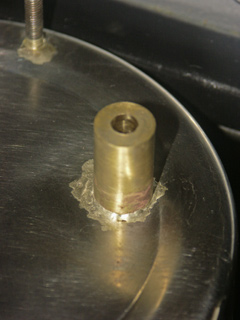
Having got the fittings in place I then bent the arms of the coil and slotted them though the holes, and soldered them in using plumbers lead free solder . . . as it melts at 200C there was no danger of the silver solder being affected. Once cooled I trimmed the tube to length and cleaned and polished the end.
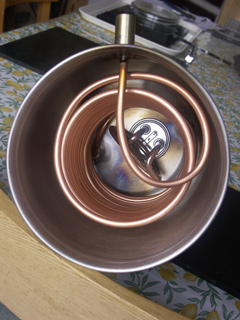
And here is the inside of the HE with the coil and the Element fitted back into place. Of course as I was fitting it back to the lid I needed to drill another hole in the lid to give me clearance for the outlet. . . plus another hole was needed to allow the plumbing to come back through . . . I sealed this with an IP66 Cable Gland.
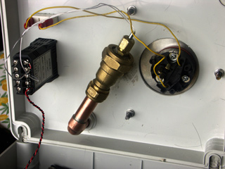
With everything in place it was time to sort the plumbing out. A Brass compression T fitting 22-15-15 . . . was fitted to the outlet, and a 22mm Compression Blanking plate with a 3mm gland soldered to it, too the temperature probe.. The Copper tube passes through the Cable gland which seals it and returns the flow outside.
With all the wiring back in place, its time to seal up the lid
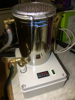
And here it is I'm proud to say . . . I have a HERMS . . . . This test was just using water pumped round the coil using the lovely little March May 809 HS pump . . . Can't wait to try it for real.
Having Acquired the Bits
TODO: List and cost Bits and Suppliers
5L Stainless Storage Container - Woolworths - 5 quid (It was during the last days of the company)
Cheapy corded Kettle - 7.99 from Morrisons . . . I used this one as it had long pins on the element, unlike some of the cheaper cordless ones that only have short pins.
10mm 6mm dia copper tube - BES . . . Coiled round a 2L PET Bottle . . . It needs to be reduced in height to fit it in, but I can do that when I have the fittings I need . . . 6mm to 15mm are not easy to find.
I thought that I had better put them all together . . . What I was after was a HERMS unit I could swap between the big and little brewery and make it 'self contained'. Using the IP56 box meant that all the electrics would be inside and not exposed . . . and as long as I seal all the holes with a suitable sealant it will retain the IP56 rating.
The first step was to decide on a position for the Heat Exchanger, and drill some holes for the studs that I was going to secure the Heat Exchanger to the lid of the box.
Turning the lid over and positioning it on the lid allowed me to mark the position of the holes on the Heat Exchanger, so I can drill them and braze in some studs.The studs are simply some 6mm stainless button headed bolts from aruncas that have been fitted through some very tight holes in the bottom of the storage container . . . I used a silver solder and flux from CuP Alloys.
The potassium fluroborate flux needs to be molten to work and this happens at about 575C . . so you are well above solder temps and need to use a MAPP gas torch . . . but the solder melts at just above 600C anyway . . . these are fairly small components so it is pretty easy to braze . . . Thicker steel and larger brass components are much harder as the heat is just absorbed. . . . They take a bit of cleaning up too
Using a Kettle element nicked from a cheapo kettle mounted in the base of the storage container so that I don't have to worry about the curve of the pot . . . plus it keeps the exposed terminals inside away from any liquid.
That's a 38mm hole, drilled with my new Bosch Cobalt Hole saws . . surprisingly easy, just take it slow and use a good cutting oil . . . with these very thin vessels it goes through easily . . . I would have preferred to use a QMax Punch but only had a 40mm which while usable was just too big to be reliable.
I also had to cut a suitable hole in the box lid to position the hole, that was fairly easy as it was just plastic and my big 64mm cheapo hole saw did the job.
You can also see that I have cut the holes for the PID Controller Auber Instruments and a Neon light to tell me when the element is 'on'. Despite me having the hole off centre (I have to make room for the outlet of the coil which will go into and out of the box), I managed to get the element pretty central in the storage container.
I suppose I should clean up the inside as well . . . when I dismantle it all to fit the coil is probably a good time. . . . Back to concentrating on the wiring . . .
Decided to fix the supply using a cable gland rather than any sort of socket . . . this means I can plug it into any spare socket. I've fitted the PID and Neon in place. The neon gets its feed from the wires that were originally connected to the kettle element. The 25A SSR is hiding on the left side . . . I will be cutting a big hole there to mount a BMF heatsink (with More Sealant required . . . Still silicone is good to 475C anyway . . .
As you can see I used the original lead supplied with the kettle . . . waste not want not.
I had a mate machine me some trick fittings to allow me to go from the 6mm tube to 15mm compression plumbing fittings. Drilled a 15mm hole in the side and base of the pot and silver soldered the brass fittings in place . . . . This wasn't easy as the brass conducts a surprising amount of heat . . . Given the amount of heat I had to use the metal of the container split when I was putting in the side fitting . . . luckily I had coated everything with the flux anyway so the silver solder flowed into the splits and sealed them . .. . Phew
Having got the fittings in place I then bent the arms of the coil and slotted them though the holes, and soldered them in using plumbers lead free solder . . . as it melts at 200C there was no danger of the silver solder being affected. Once cooled I trimmed the tube to length and cleaned and polished the end.
And here is the inside of the HE with the coil and the Element fitted back into place. Of course as I was fitting it back to the lid I needed to drill another hole in the lid to give me clearance for the outlet. . . plus another hole was needed to allow the plumbing to come back through . . . I sealed this with an IP66 Cable Gland.
With everything in place it was time to sort the plumbing out. A Brass compression T fitting 22-15-15 . . . was fitted to the outlet, and a 22mm Compression Blanking plate with a 3mm gland soldered to it, too the temperature probe.. The Copper tube passes through the Cable gland which seals it and returns the flow outside.
With all the wiring back in place, its time to seal up the lid
And here it is I'm proud to say . . . I have a HERMS . . . . This test was just using water pumped round the coil using the lovely little March May 809 HS pump . . . Can't wait to try it for real.
