


The following waffle will be of absolutely no interest whatsoever to the majority of Forum Members; some of it might be of use to anyone considering HERMS - even if you are planning a separate HERMS vessel.
In order to settle upon heat exchanger coil sizes, flow rates and so on, I did a series of experiments.
The two examples I have seen from our colonial cousins have used ½" tube and a lot of it. It is clear that the re-circulating liquor/wort must reach the same temperature as the HLT before it exits the HERMS coil. This is undesirable during the mash process as the enzymes responsible for conversion of starches to sugars will eventually be destroyed. However these system are shown to work, so they cannot be killing all the enzymes. I hope to avoid de-naturing the enzymes with a slightly more sophisticated design.
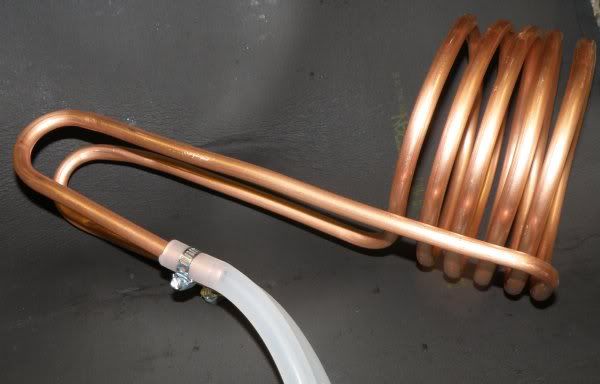
For ease of fabrication, I initially decided on 10 mm copper tube, also:
A coil of 5 turns and an average diameter of 155 mm will have a surface area of 7,750 mm and a volume of 145 ml.
A coil of 15 mm OD copper tube with the same surface area will have a volume of 240 ml.
Therefore the volume of liquor which will be static at any time will be significantly less with 10 mm tube.
(At a flow rate of 3 lpm, the liquor will be changed every 3 seconds.)
To establish feasibility of this technique, there are three stages to consider:
1. Steady state - circulation at (say) 66C
2. Ramping the temperature from (say) 50-66C
3. Ramping the temperature from (say) 66-77C
For the steady state, it would be preferable if the re-circulating liquor/wort stayed below 69C (Although some mash as high as 70C).
Likewise, for a step mash ramp, the outlet of the HERMS coil should stay below 69C, but have heat added comparatively quickly.
For the final ramp to mash-out, it does not matter if the temperature reaches at least 77C and reasonable rate of temperature rise is required.
Measurement method
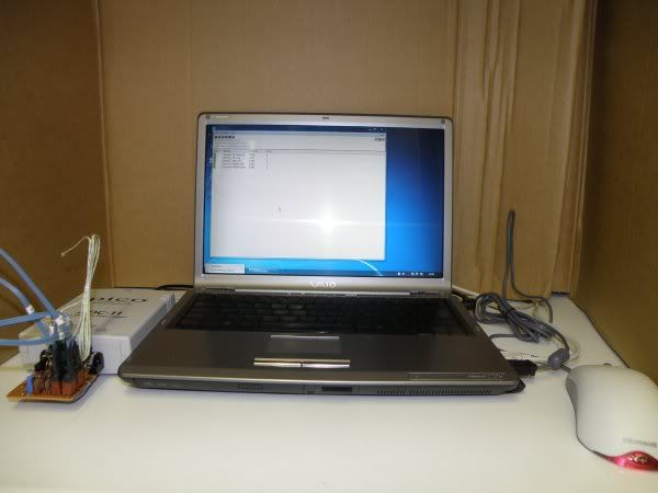
The tests were performed using an inexpensive data logger (Pico Technology ADC11 USB) and an elderly laptop. There are up to eight temperature probes made from LM35 integrated circuits. The CAZ type are accurate to +/-0.5C and the D type +/-1.0C without calibration. http://www.national.com/ds/LM/LM35.pdf.
A ninth input allows connection of an un-calibrated K-type thermocouple. By using a bare junction, it is possible to record fast changing temperatures - although the precision is not good, the relative results are more than adequate. The need for this will be shown later.
Datalogger setup:
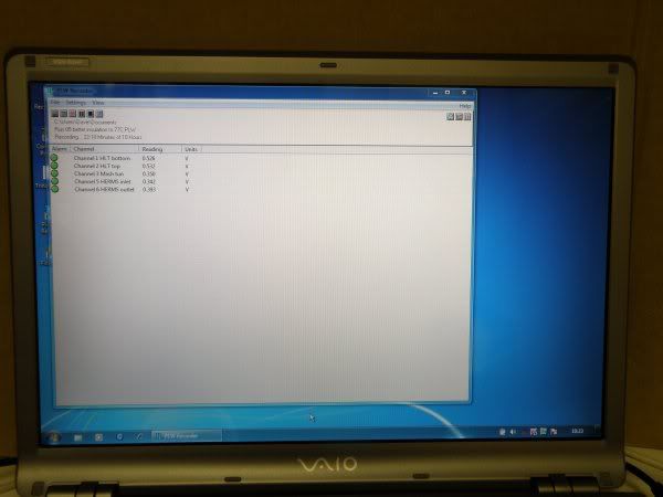
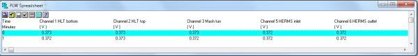
Logger screen:
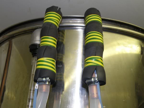
Coil ends with sensors, insulated with armaflex:
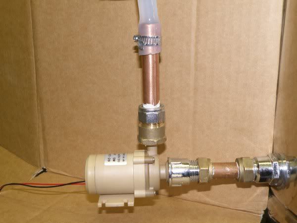
Test pump:
Procedure
The mash tun was filled with 20 litres of water - reasonably typical for a 25 litre brew, allowing for grist.
First, the flow rates obtained through the piping and test exchanger coil with a "Solar 12V 12W 5m" pump were measured at a range of voltages:
6V - 3.4 litres per minute
7.5V - 4.4 lpm
9V - 5.1 lpm
12V - 6.7 lpm
My experience with RIMS shows that a flow rate of 2 - 6 litres per minute is reasonable as long as your false bottom is good enough. Therefore the first measurements were performed at 5.5V, 3 litres per minute.
The system was run from cold with the HLT temperature controller set to 75C. The 100 litre HLT held 67 litres at the start. Data collection was set to 1 record per minute. A total of 5 probes were used for the first tests, three D-type in the HLT and mash tun and two CAZs on the inlet and outlet of the heat exchanger coil.
Because the probes give 10mV/C, the vertical scale of the graphs is multiplied by 100.
First results
The probes were placed in an isothermal environment to check cross calibration, they were within 0.1C of each other.
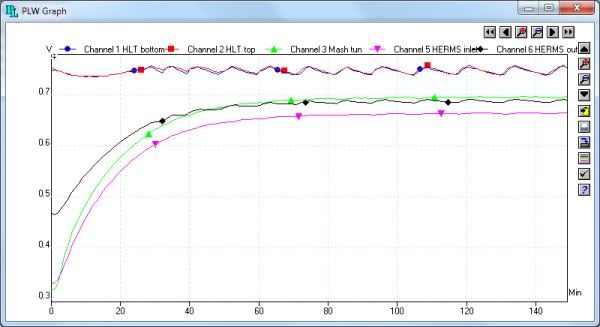
With HLT at nominally 74C, first ramp of mash tun from 32C to 69C:
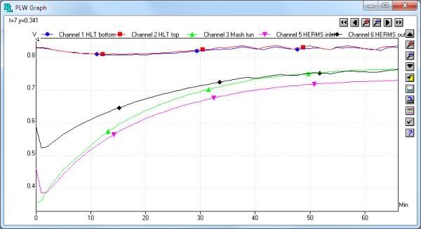
With HLT at nominally 83C, mash tun ramp from 37C to 77C:
In these tests it is shown:
Ramp time from 50C to 66C HLT 74C = 28 mins, HLT 83C = 16 mins
(0.57 and 1.0 C per minute - It has been said that the "big boys" aim for 0.5C/min)
Typical temperature differential between mash and HE Coil inlet = 3.5C
Temperature differential between maximum mash and HLT = 6 - 7C (which is due to losses in re-circulating system)
At HLT = 74C, the HERMS outlet never exceeds 69C
Time to raise HLT from 74 to 83C = 30 mins (measured, not shown on above graphs)
Time to raise mash from 70C to 77C = 30 mins (allowing for the addition of about 7L first batch sparge) - slow but workable, particularly with 90 min mash. The last 30 mins of mashing could be ramping as well.
Temperature gradient or stratification in the HLT is negligible due to convection currents caused by frequent HLT heater operation - to compensate for removal of heat by the exchanger.
Conclusions after first tests
The choice of size for the first test coil was extremely lucky, or does not matter much!
Not all the above results will be correct once the temperature is controlled by variation of total flow through the exchanger coil.
These results are enough to try adding a solenoid valve, PID and probe.
At this point I was confident that something would be made to work, so I modified my existing HLT and built a new control panel.
Practical build
The sight tube on my HLT reads down to about 13 litres and to prevent the elements running dry, I seldom go below this. The second batch sparge for a 25 litre brew is usually about 16 litres. This means that I would have 29 litres minimum in the HLT after the first batch sparge and mashing out at 77C. For practical reasons, I am placing the exchanger coil vertically with its top at roughly the 30 litre point.
Inside HLT:
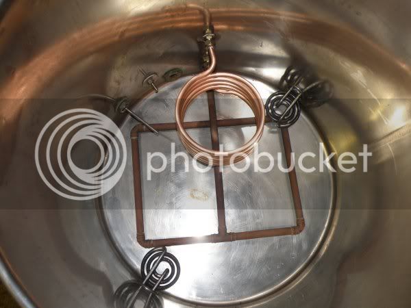
If the next results show that it is necessary, I can increase the diameter of the coil, or add a few more turns and have the choice of two lengths - this would then use an extra solenoid valve.
And here comes a gotcha!
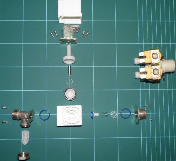
Four solenoid valves appear from China.
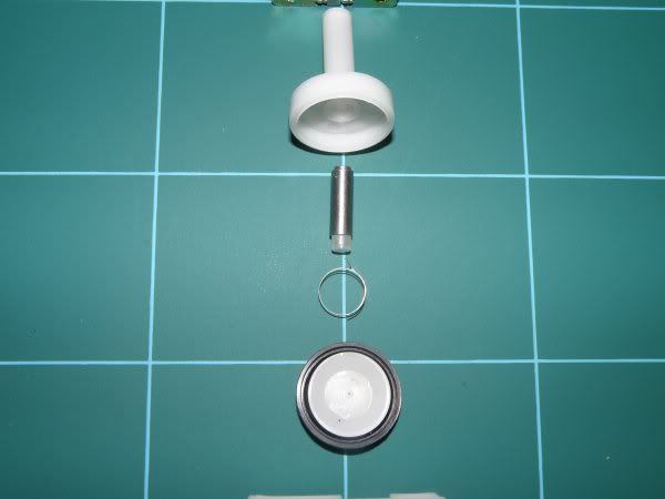
As described, they are servo valves which rely on a very small hole which the solenoid actuator opens to allow the main diaphragm to move under the pressure of the incoming pumped liquid. The actuator is within the fluid and would therefore be very likely to seize up with sticky wort.
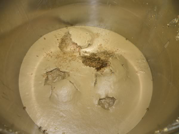
There is also a very fine filter in the inlet port; it looks like it can be removed and replaced the other way round (i.e. a built-in spare).
However, if your grain has this much "dust", or simply at the beginning of circulation, it will more than likely block quickly.
Anyway, the valve is easy to disassemble and the next tests could be tried with water rather than wort. Once the system operation has been established flow control method could be established, but
How else to control flow? Full flow non-servo valve, Zone valve, Rotary or linear shuttle valve - expensive.
How else to pump? Archimedes screw, bucket lift, waterwheel, peristaltic - squeeze a soft tube..
Squeeze with what? - solenoid, motor, windscreen wiper motor, car door lock or window motor.. still needs some force. A folded pipe stops flow. It requires much less force to fold and unfold a pipe than to squash it.
Disadvantages - comparatively large, wears, might fracture.
Advantages - nearly full flow, unlikely to block, very easy to clean, very cheap and easy to replace tube.
Getting a bit more clever you could fold one tube while unfolding another - two way, maybe even proportional - one tube feeds exchanger coil, one bypasses - future development potential.
See the posting on Valves for the final result.
Some pros and cons of PT100 probes in this test environment
By now, you will all appreciate that uncompensated thermocouple probes are far less accurate than PlaTinum resistance probes. Without individual calibration, meters with thermocouples can easily read as much as 4 degrees out - this can make a massive difference to your mash, nominally 62-70C. Therefore PT100 probes are considerably more easy to use, and are essentially interchangeable.
This is quite a good basic overview but there are many others:
http://www.iqinstruments.com/iqshop/tec ... pt100.html
The key which is of interest for some of these measurements and which is alluded to here is "response time". This is a potential problem with any sheathed sensor and PT100 probes become considerably more difficult to obtain with a very small physical size. I have a range of PT100 sensor elements to hand, but nothing which I can make small enough while still reasonably rugged.
The sheath will cause an averaging of the temperature reading if it is changing quickly. This is an advantage in the PID feedback system as a whole, but it also means that we cannot see the instantaneous temperature of the re-circulating wort as it leaves the exchanger coil. Therefore, without a different temperature measurement method, we do not know the maximum temperature the wort has reached. This is why an input for a K-type thermocouple has been allowed on the data logger. A thermocouple may not be inherently accurate, but a bare junction will have a very fast response to temperature change and can be calibrated against the know good slower response IC sensors and PT100s.
In order to settle upon heat exchanger coil sizes, flow rates and so on, I did a series of experiments.
The two examples I have seen from our colonial cousins have used ½" tube and a lot of it. It is clear that the re-circulating liquor/wort must reach the same temperature as the HLT before it exits the HERMS coil. This is undesirable during the mash process as the enzymes responsible for conversion of starches to sugars will eventually be destroyed. However these system are shown to work, so they cannot be killing all the enzymes. I hope to avoid de-naturing the enzymes with a slightly more sophisticated design.
For ease of fabrication, I initially decided on 10 mm copper tube, also:
A coil of 5 turns and an average diameter of 155 mm will have a surface area of 7,750 mm and a volume of 145 ml.
A coil of 15 mm OD copper tube with the same surface area will have a volume of 240 ml.
Therefore the volume of liquor which will be static at any time will be significantly less with 10 mm tube.
(At a flow rate of 3 lpm, the liquor will be changed every 3 seconds.)
To establish feasibility of this technique, there are three stages to consider:
1. Steady state - circulation at (say) 66C
2. Ramping the temperature from (say) 50-66C
3. Ramping the temperature from (say) 66-77C
For the steady state, it would be preferable if the re-circulating liquor/wort stayed below 69C (Although some mash as high as 70C).
Likewise, for a step mash ramp, the outlet of the HERMS coil should stay below 69C, but have heat added comparatively quickly.
For the final ramp to mash-out, it does not matter if the temperature reaches at least 77C and reasonable rate of temperature rise is required.
Measurement method
The tests were performed using an inexpensive data logger (Pico Technology ADC11 USB) and an elderly laptop. There are up to eight temperature probes made from LM35 integrated circuits. The CAZ type are accurate to +/-0.5C and the D type +/-1.0C without calibration. http://www.national.com/ds/LM/LM35.pdf.
A ninth input allows connection of an un-calibrated K-type thermocouple. By using a bare junction, it is possible to record fast changing temperatures - although the precision is not good, the relative results are more than adequate. The need for this will be shown later.
Datalogger setup:
Logger screen:
Coil ends with sensors, insulated with armaflex:
Test pump:
Procedure
The mash tun was filled with 20 litres of water - reasonably typical for a 25 litre brew, allowing for grist.
First, the flow rates obtained through the piping and test exchanger coil with a "Solar 12V 12W 5m" pump were measured at a range of voltages:
6V - 3.4 litres per minute
7.5V - 4.4 lpm
9V - 5.1 lpm
12V - 6.7 lpm
My experience with RIMS shows that a flow rate of 2 - 6 litres per minute is reasonable as long as your false bottom is good enough. Therefore the first measurements were performed at 5.5V, 3 litres per minute.
The system was run from cold with the HLT temperature controller set to 75C. The 100 litre HLT held 67 litres at the start. Data collection was set to 1 record per minute. A total of 5 probes were used for the first tests, three D-type in the HLT and mash tun and two CAZs on the inlet and outlet of the heat exchanger coil.
Because the probes give 10mV/C, the vertical scale of the graphs is multiplied by 100.
First results
The probes were placed in an isothermal environment to check cross calibration, they were within 0.1C of each other.
With HLT at nominally 74C, first ramp of mash tun from 32C to 69C:
With HLT at nominally 83C, mash tun ramp from 37C to 77C:
In these tests it is shown:
Ramp time from 50C to 66C HLT 74C = 28 mins, HLT 83C = 16 mins
(0.57 and 1.0 C per minute - It has been said that the "big boys" aim for 0.5C/min)
Typical temperature differential between mash and HE Coil inlet = 3.5C
Temperature differential between maximum mash and HLT = 6 - 7C (which is due to losses in re-circulating system)
At HLT = 74C, the HERMS outlet never exceeds 69C
Time to raise HLT from 74 to 83C = 30 mins (measured, not shown on above graphs)
Time to raise mash from 70C to 77C = 30 mins (allowing for the addition of about 7L first batch sparge) - slow but workable, particularly with 90 min mash. The last 30 mins of mashing could be ramping as well.
Temperature gradient or stratification in the HLT is negligible due to convection currents caused by frequent HLT heater operation - to compensate for removal of heat by the exchanger.
Conclusions after first tests
The choice of size for the first test coil was extremely lucky, or does not matter much!
Not all the above results will be correct once the temperature is controlled by variation of total flow through the exchanger coil.
These results are enough to try adding a solenoid valve, PID and probe.
At this point I was confident that something would be made to work, so I modified my existing HLT and built a new control panel.
Practical build
The sight tube on my HLT reads down to about 13 litres and to prevent the elements running dry, I seldom go below this. The second batch sparge for a 25 litre brew is usually about 16 litres. This means that I would have 29 litres minimum in the HLT after the first batch sparge and mashing out at 77C. For practical reasons, I am placing the exchanger coil vertically with its top at roughly the 30 litre point.
Inside HLT:
If the next results show that it is necessary, I can increase the diameter of the coil, or add a few more turns and have the choice of two lengths - this would then use an extra solenoid valve.
And here comes a gotcha!
Four solenoid valves appear from China.
As described, they are servo valves which rely on a very small hole which the solenoid actuator opens to allow the main diaphragm to move under the pressure of the incoming pumped liquid. The actuator is within the fluid and would therefore be very likely to seize up with sticky wort.
There is also a very fine filter in the inlet port; it looks like it can be removed and replaced the other way round (i.e. a built-in spare).
However, if your grain has this much "dust", or simply at the beginning of circulation, it will more than likely block quickly.
Anyway, the valve is easy to disassemble and the next tests could be tried with water rather than wort. Once the system operation has been established flow control method could be established, but
How else to control flow? Full flow non-servo valve, Zone valve, Rotary or linear shuttle valve - expensive.
How else to pump? Archimedes screw, bucket lift, waterwheel, peristaltic - squeeze a soft tube..
Squeeze with what? - solenoid, motor, windscreen wiper motor, car door lock or window motor.. still needs some force. A folded pipe stops flow. It requires much less force to fold and unfold a pipe than to squash it.
Disadvantages - comparatively large, wears, might fracture.
Advantages - nearly full flow, unlikely to block, very easy to clean, very cheap and easy to replace tube.
Getting a bit more clever you could fold one tube while unfolding another - two way, maybe even proportional - one tube feeds exchanger coil, one bypasses - future development potential.
See the posting on Valves for the final result.
Some pros and cons of PT100 probes in this test environment
By now, you will all appreciate that uncompensated thermocouple probes are far less accurate than PlaTinum resistance probes. Without individual calibration, meters with thermocouples can easily read as much as 4 degrees out - this can make a massive difference to your mash, nominally 62-70C. Therefore PT100 probes are considerably more easy to use, and are essentially interchangeable.
This is quite a good basic overview but there are many others:
http://www.iqinstruments.com/iqshop/tec ... pt100.html
The key which is of interest for some of these measurements and which is alluded to here is "response time". This is a potential problem with any sheathed sensor and PT100 probes become considerably more difficult to obtain with a very small physical size. I have a range of PT100 sensor elements to hand, but nothing which I can make small enough while still reasonably rugged.
The sheath will cause an averaging of the temperature reading if it is changing quickly. This is an advantage in the PID feedback system as a whole, but it also means that we cannot see the instantaneous temperature of the re-circulating wort as it leaves the exchanger coil. Therefore, without a different temperature measurement method, we do not know the maximum temperature the wort has reached. This is why an input for a K-type thermocouple has been allowed on the data logger. A thermocouple may not be inherently accurate, but a bare junction will have a very fast response to temperature change and can be calibrated against the know good slower response IC sensors and PT100s.