Robbo's Raspberry Pi Dual Element Boiler/HLT Controller
This How-To Guide will show you how to use a £25 Raspberry Pi mini computer to control a home-made Dual Element Tesco Kettle HLT/Boiler (see the introduction below for full capability). The actual hardware being brought together in this guide are very versatile, and can not only act as an HLT/Boiler Controller, but could also be used for many other tasks, such as a fridge/heater Controller (with some minor changes to the software). In fact, the device is so flexible, it would be quite possible to get the device to control a fridge with a continously changing user defined temperature profile, data-log the temperatures, then display the data graphically over the internet for you to monitor from your iPhone.
This guide is intended for anyone who has basic computer skills and basic electronic skills (i.e. anyone who can follow a simple wiring diagram, do some soldering, and use Microsoft Windows). The software installation side of the guide is written in a step by step fashion, covering every key-press required to get the device working, so it should be simple to follow.
It should be noted however, that this guide does involve wiring mains voltage components, which is dangerous if not done correctly.
The author accepts no responsibility for anyone injuring themselves (or worse) using this guide. Please treat mains electricity with the respect it deserves, IT CAN KILL!
Contents of this How-To Guide
Post 1 - Introduction
Post 2 - How to Build Your Device
Post 3 - Raspberry Pi Software Installation
Post 4 - Running Software for the First Time
Post 5 - Making Software Run at Boot-Up
Post 5 - Frequently Asked Questions
1) Introduction
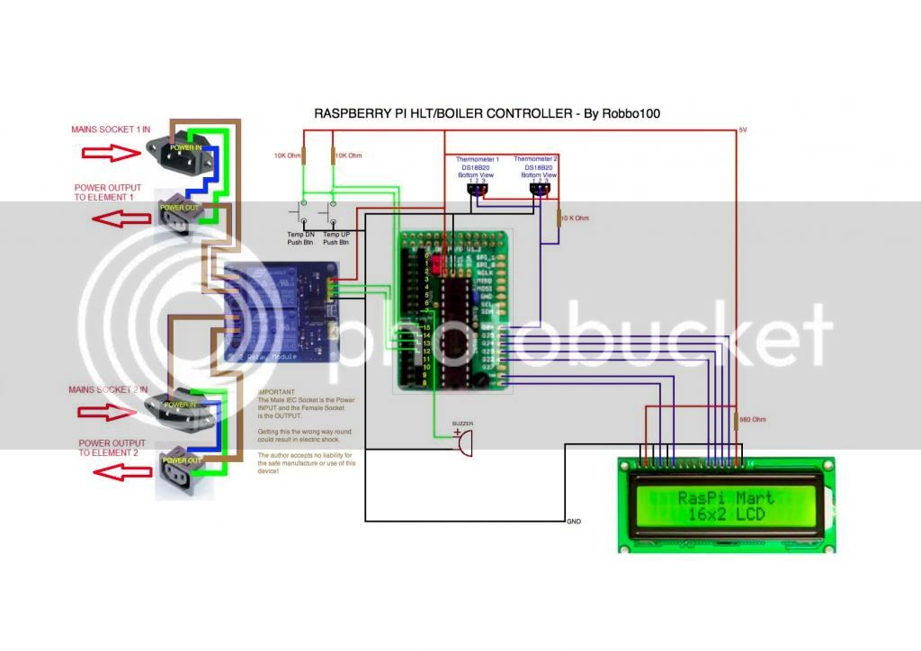
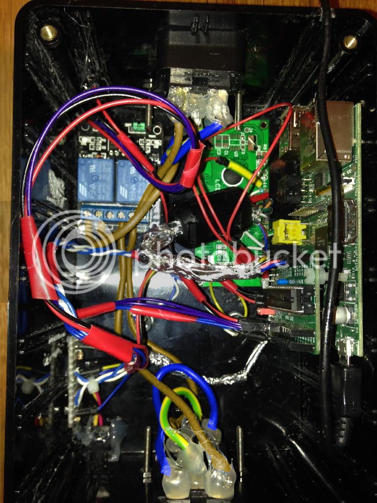
The device in this guide, is essentially a very low cost (£25) credit card sized computer, which is connected to some external devices to make it useful. The connected devices are, two push button switches, two thermometers, a simple text display (two lines of 16 characters), and two relays which can switch mains power devices of up to 10 Amps each (e.g. two kettle elements, or a fridge and a heater).
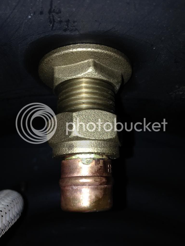
For this guide, I will explain how to build the device, and how to load some code (that I have already written for you) to make a Boiler/HLT Controller. I have very successfully used this to control my DIY plastic Boiler/HLT, which is heated by two Tesco Extra Value Kettle elements (each powered from a different 13A plug). The device has made a massive difference to my brew-day, because it means I donât have to keep monitoring the temperatures, starting stopwatches etc. It just sorts it all out for me, all the way from the mash to the cool down.
It should be noted that I am using two 2.2 kW Tesco extra value kettles, one connected to each of the two relays, which will draw under slightly under 10A each (the kettles were supplied with 10A rated power cords), however, if you are using elements rated any higher, e.g. a 2.4 kW element, then you will need to use high specification relays (and IEC kettle sockets/plugs) than me (I have provided an example of such a relay in the component list below). Using too low a relay specification will lead to over-heating, and potentially fire or other damage.
YOU DO NOT NEED TO UNDERSTAND HOW TO WRITE ANY SOFTWARE, however, for background information (for anyone interested), the software is written in Python, which I coded onto the Pi remotely using WebIDE. WebIDE is an amazingly useful bit of software that allows you to connect to the Pi from another computer and program the Pi through your Chrome web browser.
The Python script runs automatically at boot and doesn't need a monitor or keyboard. There is no user intervention required, just power it on, wait 20 seconds for it to boot, and off you go!
Here is a List of Functions of the Pre-Written Software:
[*]Boiler Mode:
Future Development Potential
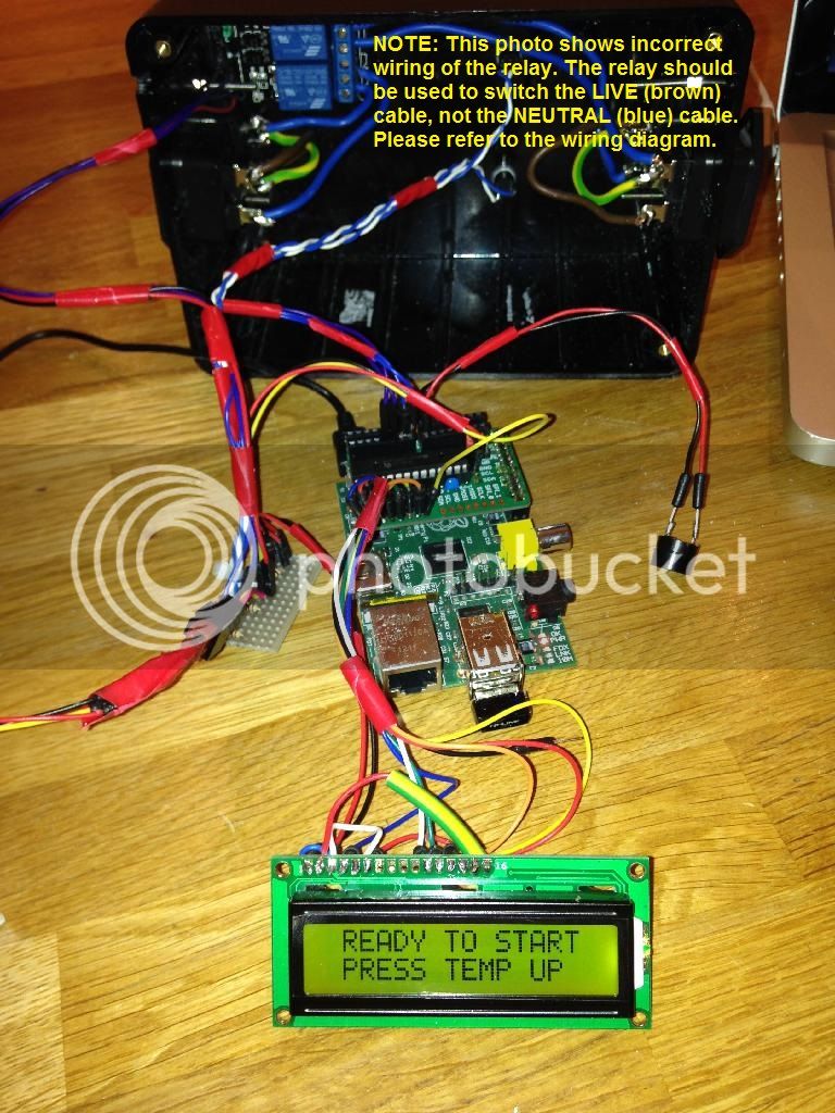
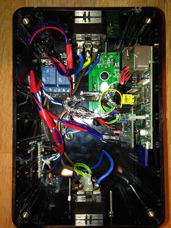
Some photos of the device in action:
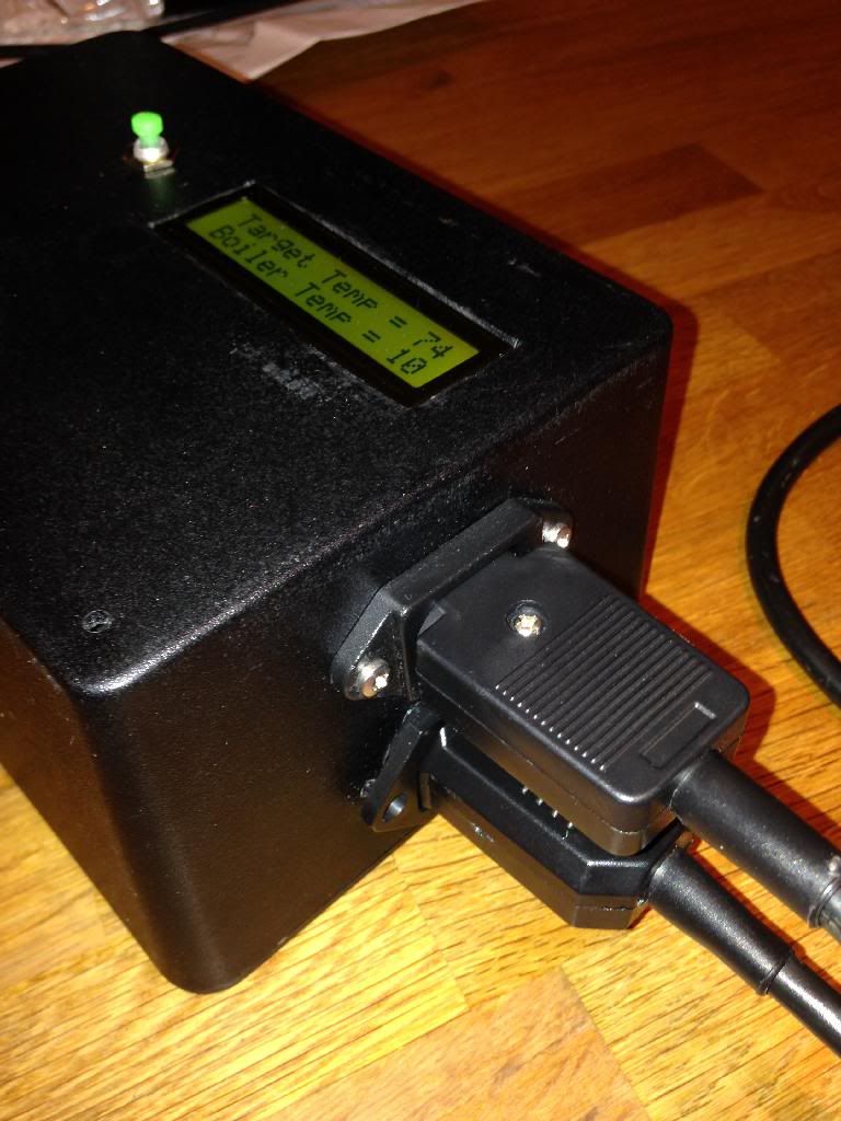
In HLT Mode:
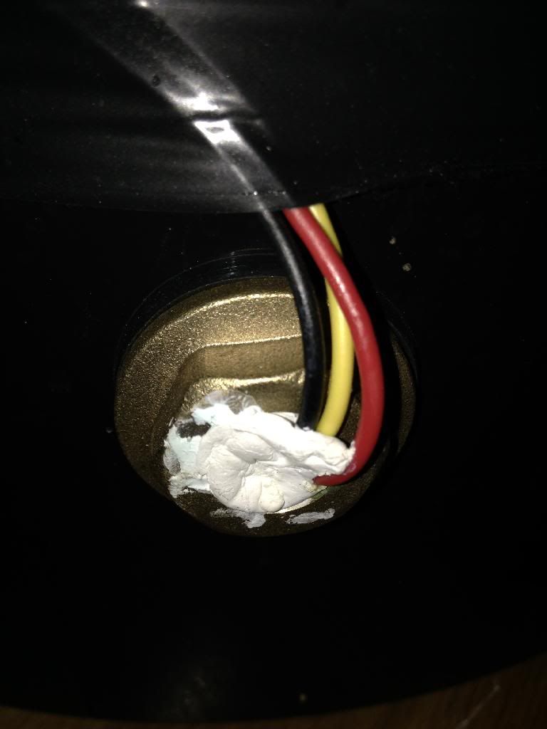
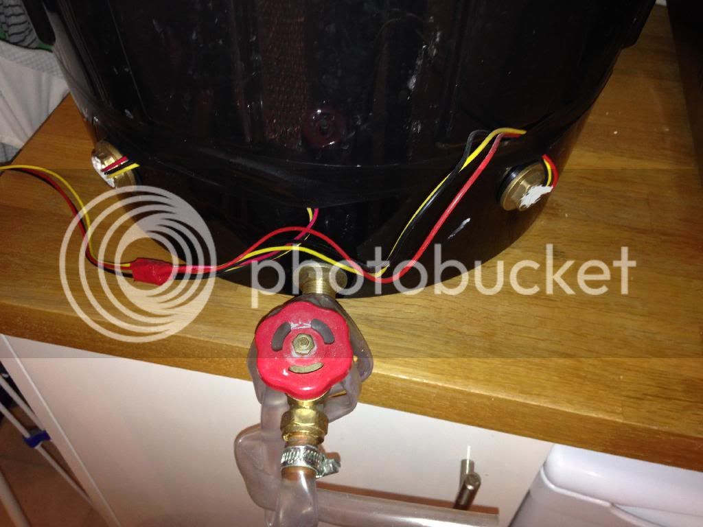
Connected to the boiler:
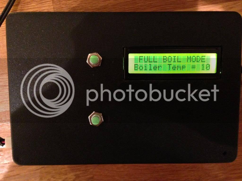
Full Boil Mode:
This How-To Guide will show you how to use a £25 Raspberry Pi mini computer to control a home-made Dual Element Tesco Kettle HLT/Boiler (see the introduction below for full capability). The actual hardware being brought together in this guide are very versatile, and can not only act as an HLT/Boiler Controller, but could also be used for many other tasks, such as a fridge/heater Controller (with some minor changes to the software). In fact, the device is so flexible, it would be quite possible to get the device to control a fridge with a continously changing user defined temperature profile, data-log the temperatures, then display the data graphically over the internet for you to monitor from your iPhone.
This guide is intended for anyone who has basic computer skills and basic electronic skills (i.e. anyone who can follow a simple wiring diagram, do some soldering, and use Microsoft Windows). The software installation side of the guide is written in a step by step fashion, covering every key-press required to get the device working, so it should be simple to follow.
It should be noted however, that this guide does involve wiring mains voltage components, which is dangerous if not done correctly.
The author accepts no responsibility for anyone injuring themselves (or worse) using this guide. Please treat mains electricity with the respect it deserves, IT CAN KILL!
Contents of this How-To Guide
Post 1 - Introduction
Post 2 - How to Build Your Device
Post 3 - Raspberry Pi Software Installation
Post 4 - Running Software for the First Time
Post 5 - Making Software Run at Boot-Up
Post 5 - Frequently Asked Questions
1) Introduction
The device in this guide, is essentially a very low cost (£25) credit card sized computer, which is connected to some external devices to make it useful. The connected devices are, two push button switches, two thermometers, a simple text display (two lines of 16 characters), and two relays which can switch mains power devices of up to 10 Amps each (e.g. two kettle elements, or a fridge and a heater).
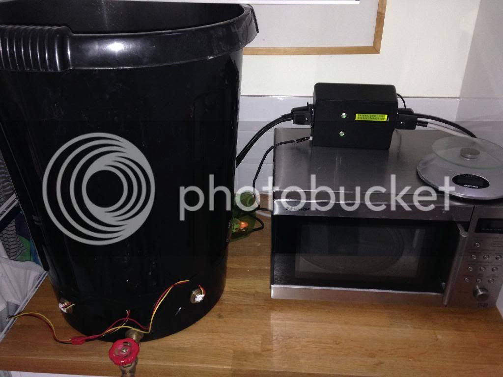
For this guide, I will explain how to build the device, and how to load some code (that I have already written for you) to make a Boiler/HLT Controller. I have very successfully used this to control my DIY plastic Boiler/HLT, which is heated by two Tesco Extra Value Kettle elements (each powered from a different 13A plug). The device has made a massive difference to my brew-day, because it means I donât have to keep monitoring the temperatures, starting stopwatches etc. It just sorts it all out for me, all the way from the mash to the cool down.
It should be noted that I am using two 2.2 kW Tesco extra value kettles, one connected to each of the two relays, which will draw under slightly under 10A each (the kettles were supplied with 10A rated power cords), however, if you are using elements rated any higher, e.g. a 2.4 kW element, then you will need to use high specification relays (and IEC kettle sockets/plugs) than me (I have provided an example of such a relay in the component list below). Using too low a relay specification will lead to over-heating, and potentially fire or other damage.
YOU DO NOT NEED TO UNDERSTAND HOW TO WRITE ANY SOFTWARE, however, for background information (for anyone interested), the software is written in Python, which I coded onto the Pi remotely using WebIDE. WebIDE is an amazingly useful bit of software that allows you to connect to the Pi from another computer and program the Pi through your Chrome web browser.
The Python script runs automatically at boot and doesn't need a monitor or keyboard. There is no user intervention required, just power it on, wait 20 seconds for it to boot, and off you go!
Here is a List of Functions of the Pre-Written Software:
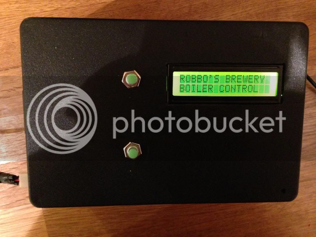
- Changeable Welcome Screen at boot[/*:m:3lw4jer9]
- Two primary functions, HLT Mode and Boiler Mode[/*:m:3lw4jer9]
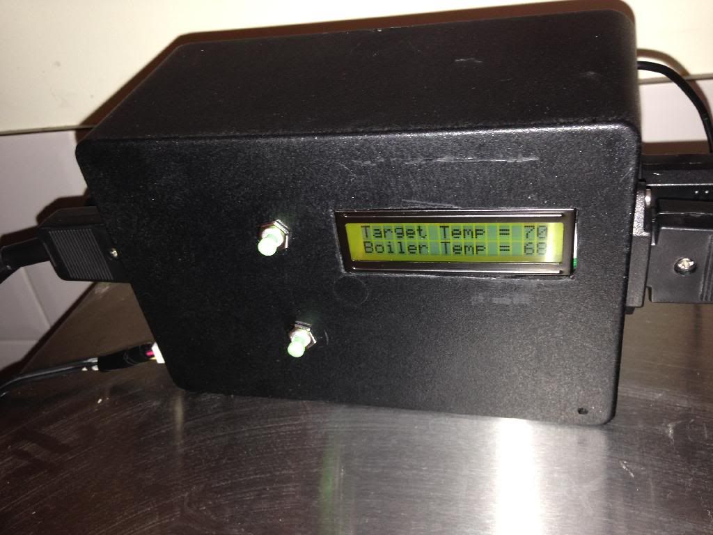
- HLT Mode:
[list:3lw4jer9] - Display shows the target HLT temperature and current boiler temperature[/*:m:3lw4jer9]
- When target temperature is reached, the elements are switched off (and then one element is used intermittently to maintain temperature)[/*:m:3lw4jer9]
- Audio alarm is triggered when target temperature is reached[/*:m:3lw4jer9]
- Target temperature can be varied using Temperature UP and DOWN buttons (alarm function is reset if the target temperature is changed if the alarm has already gone off)[/*:m:3lw4jer9]
[*]Boiler Mode:
- System is commanded to Boiler Mode by pressing both temperature control buttons at the same time[/*:m:3lw4jer9]
- System turns both elements on[/*:m:3lw4jer9]
- When boil established (96 deg C), alarm is triggered (to prompt bitter hops) display then shows a countdown from 59:59 down to 00:00[/*:m:3lw4jer9]
- At 15:00 remaining, alarm is triggered again, for aroma hops prompt[/*:m:3lw4jer9]
- At 00:00 the alarm is sounded again and display prompts to go into cooling mode[/*:m:3lw4jer9]
- When Temperature Down button pressed, both elements turn off, and display shows the boiler temperature[/*:m:3lw4jer9]
- When 28 degrees is reached, the alarm is sounded again to alert the completion of the cooling cycle[/*:m:3lw4jer9]
Future Development Potential
- I would like to add a run-dry detection function to turn off the elements when the fluid levels go below a certain point (useful safety feature during the sparge).[/*:m:3lw4jer9]
- I will probably add a function to cycle one of the elements off during the boil to reduce the strength of the boil (and save electricity).[/*:m:3lw4jer9]
- I might write some software to make the device act as a brewing fridge/heater controller, but I would need some convincing that there are enough users wanting it (since I donât have a brewing fridge myself).[/*:m:3lw4jer9]
Some photos of the device in action:
In HLT Mode:
Connected to the boiler:
Full Boil Mode: