bobsbeer
Well-Known Member
I was planning on using separate buttons as the screen I've ordered is a 4 x 64 one. I have some mini buttons to use. Never thought of using the serial port. Maybe try that tomorrow when I have some time.


Belter said:I tested this today. When I press the reset button and the relay loses power for a second it opens the solenoid. This is something I'm going to have to look into when I get a min.
Is there an easy way of getting the LCD to display "Target hit" etc and then pause for say 5 seconds then revert to the beginning? That way I wouldn't have to reset each time.
I got rather wet. As did my arduino.
It seems to be overshooting by 600ml. I didn't test it on mains, it was on my garden tap at half power so when I get a proper supply into my brewery i'll check for sure. But... if 600ml is standard then I'll amend the code to start at 600ml and count up from there never going below 600ml. If I were to calibrate it to compensate for this then at different total volumes it would be out by quite a bit so I think it's best to get an average overshoot (from the solenoid closing) and add this to the figure.
Otherwise it was pretty cool and when it's boxed up will be really good.
I assume I can keep the same LCD but not cut out the buttons from the enclosure and either solder new buttons in parallel with the old buttons or just re-code it to target a different pin and put a button and pull up resistor on it?
Belter said:Is there an easy way of getting the LCD to display "Target hit" etc and then pause for say 5 seconds then revert to the beginning? That way I wouldn't have to reset each time.
Belter said:I got rather wet. As did my arduino.
It seems to be overshooting by 600ml. I didn't test it on mains, it was on my garden tap at half power so when I get a proper supply into my brewery i'll check for sure. But... if 600ml is standard then I'll amend the code to start at 600ml and count up from there never going below 600ml. If I were to calibrate it to compensate for this then at different total volumes it would be out by quite a bit so I think it's best to get an average overshoot (from the solenoid closing) and add this to the figure.
Otherwise it was pretty cool and when it's boxed up will be really good.
I assume I can keep the same LCD but not cut out the buttons from the enclosure and either solder new buttons in parallel with the old buttons or just re-code it to target a different pin and put a button and pull up resistor on it?
")
Fil said:u may beat steve to finishing the project
Belter said:£6.28 +vat and any delivery from cpc farnell
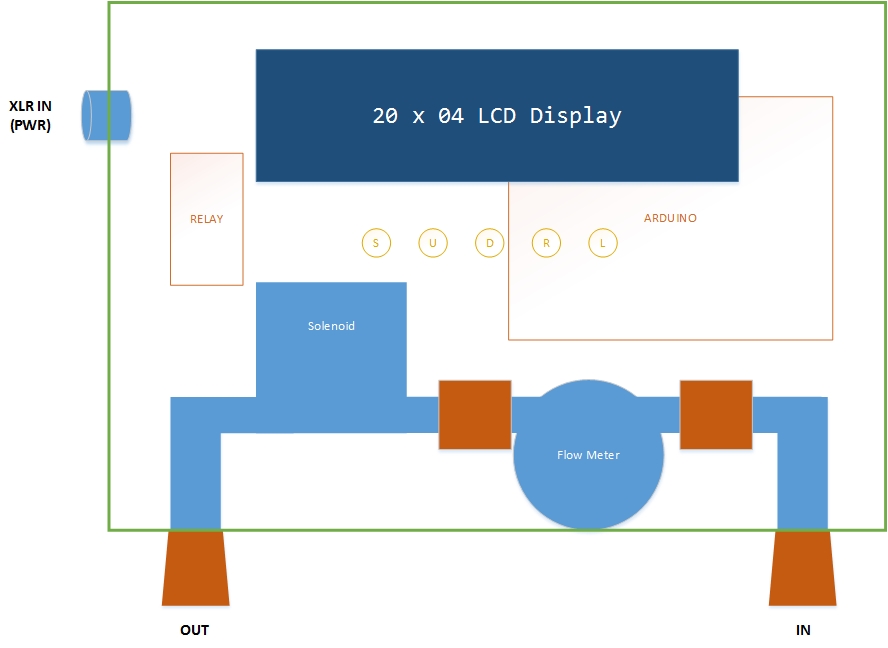
Steve have you got a box lined up for this yet?
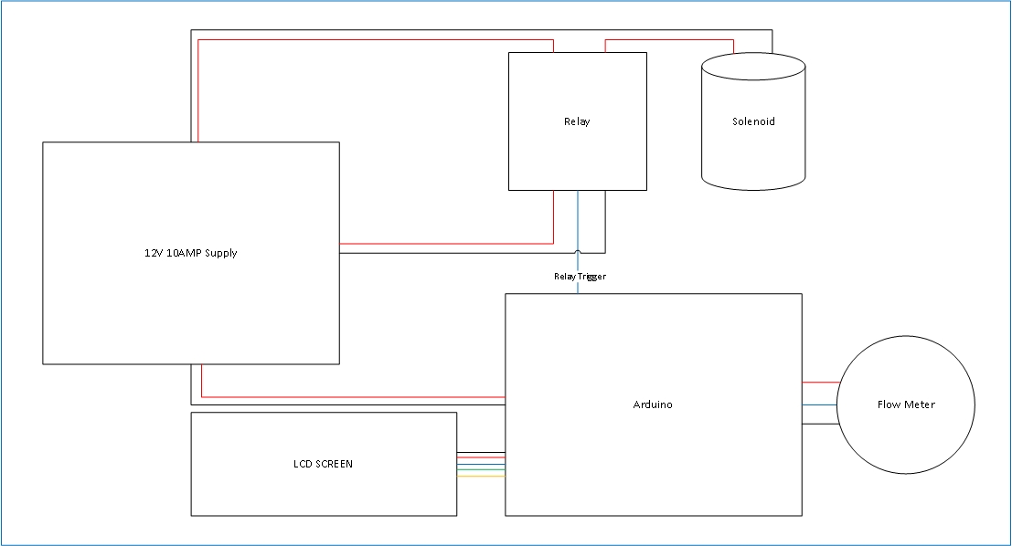
I see on your diagram that you only have one power supply (xlr, which I assume now is USB?). Do you plan on having more? I'm still stuck with three at the minute.
Belter said:I see they do other sizes as well in the description. Surely it will need to be at least that big to house your power supply?
Do you know how many amps cat5 can carry? I'd at you'd be well short of your 10A requirement. If you used it to power your Arduino etc you'd need to put in control fuses.
Enter your email address to join: