Flow Controller

The Homebrew Forum

Help Support The Homebrew Forum:

This site may earn a commission from merchant affiliate links, including eBay, Amazon, and others.
Hadn't thought of that scenario. I'll look into getting some more substantial cabling before I start to build (Never heard of cable referred to as YY before).
 
YY is a type of flex we use in industry for control cabling. We also use it for domestic central heating.

It's cheap but is very much like any old white flex with the cores numbered instead of coloured. There's SY, YY, NY. All sorts of Y's all different applications.
 
The build has begun. Fettled a ATX power supply this evening with the load resistor. So that should be enough to power the arduino, pump and all the other peripherals I can possibly think of. Just waiting for the banana sockets and plugs then it's ready to go. New soldering iron worked a treat. Monday hopefully I can put the pressure sensor board together once I get all the capacitors. Then we are nearly ready to rock. Testing anyway. I still need a 40mm qmax to sort the heating element in the new HLT.
 
bobsbeer said:
The build has begun. Fettled a ATX power supply this evening with the load resistor. So that should be enough to power the arduino, pump and all the other peripherals I can possibly think of. Just waiting for the banana sockets and plugs then it's ready to go. New soldering iron worked a treat. Monday hopefully I can put the pressure sensor board together once I get all the capacitors. Then we are nearly ready to rock. Testing anyway. I still need a 40mm qmax to sort the heating element in the new HLT.

Good job :thumb: Keep us updated with lots of photos :)

What soldering iron did you pick up out of interest? Thinking of getting one so I can return the one I've borrowed!
 
I got the Maplin variable temp one. £15. Works well, but how long it will last, who knows. The longevity was not one of the review strong points, but others said it was fine, so rather than have one shipped from China I got that that one. http://www.maplin.co.uk/50w-solder-station-35016 Maybe in future I'll go for one with an LCD, but as a newbie solderer, and only in the past ever used a very cheap single heat iron, it is a joy to use.
 
Now I have my power supply I tested the motorised valve. The opening and closing time with no load is about 2 seconds, so should work really well. But I'm having a senior moment on how to connect in the DPDT relay to make this work. The valve if closed needs red to + and blue to -. It then opens and stays open. Reverse the connection and it closes and stays closed. The power can be disconnected, and probably should be after each actuation forward or reverse. Stopping the power during actuation stops the valve mid way, and when reconnected continues to fully open or closed depending on the polarity of the connection. This also gives rise to the possibility of flow control, but that's for another time. For now I just want to make this open and close. So what sort of control circuit do I need? I figure it needs a pulse to the relay of x seconds to operate the relay. Pulse again for x seconds and as the relay is now open, pulse again should close it. But what pins on the relay do I need to connect?
 
Ive been waiting for your report and eyeing the ebay ads for said valves with an itchy mouse finger..

for simplicitys sake i would just time out the control voltage for now picking a safe time in which it should close or open fully. tho you could query the flow controller for movement to determin the valve state.

the actual switching has been bugging me since we first scratched heads about it.. the schematic in the ad looks so simple, but ;)
dont think you can avoid using a diode or 2 to ensure current flow in one direction when wiring -ve and +ve feeds to the motor poles. but any solutions i start thinking about soon balloon out of proportion, copying a simple circuit is one thing designing it is another ;)
 
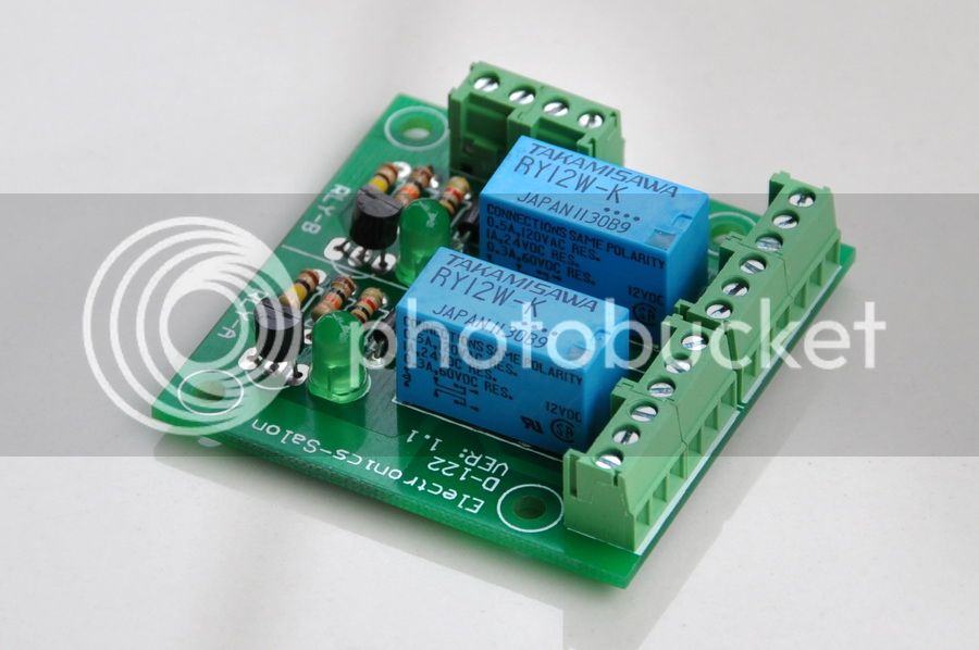
I asked about it on the Arduino forum. A member has found THIS

D-122-12VTA1.jpg


This board would be able to operate 2 valves independently from the arduino outputs. So that solves water to HLT and water out to MT. I was surprised how fast the valve opened and closed. Way less than 5 seconds with no load. But in working conditions the time may be dependant on the pressure in the pipe. I'm not sure it would be good to keep the power on to the valve all the time, but a set time of 5-10 seconds would be all it needed to open or close. Our operations don't need it to cycle between states in less than that time as it would take a few minutes to transfer the volume. So it could power down between operations. So, power on valve OPEN, stay powered on for 5-10 seconds then power off for the time it takes to fill the HLT. Volume reached, (high signal from pressure sensor) power on, valve CLOSES, stay powered on for 5-10 seconds then power off. I hope that makes sense. :grin:

My Uno has 14 digital outputs, so with full automation with 9 valves, 1 pump, 2 SSR, that only uses 12. But the one wire temp probes also go through the digital I/O don't they? I figure I need 3 temp probes. 1 HLT, 1 MT HERMES, 1 counter chiller. I may have to monitor the chiller temp by hand. Bummer. And then there is the output to the LCD. Not figured how many that will need. I need a MegaMega. :grin:
 
Just had another thought. Another person has said that I will need a second relay to turn the power on and off after the change of state. Makes sense as the 12v power is not disconnected via the DPDT relays. I'm not sure if this is included in the valves internal electrics but I'm assuming not. I might have to take my valve apart to see if it has a relay.
 
Update on the valve. It does have an 'auto power off' after opening and closing. I tested this with my multimeter in series on amps. After opening or closing it goes to zero. So at least I don't need 2 relays. Another Arduinoist has also suggested using an L239 chip. I found a shield which in theory should be able to control 4 motors or in our case valves. Seems like a good solution.

I also came across this code which could be amended by taking the switch and pot out and controlling the valve from the pressure sensor output.

HERE
 
The one wire temp probes only connect to 1 digital in port, you can have all of them all on say pin 9, you just need to assign each one their address in the code :)
 
Ah yes I remember now, so at least the pins should be enough. The problem with the uno rather than a mega may be the memory for the code. But we will see. I'll worry about that bit later.
 
Looks like your making good progress Bob.. to increase the number of io pins u can use on the controller board, you can use a serial coms protocol over 3 wires to the lcd screen pm me for details... slightly different lcd lib and commands..

would a stepper motor control board be any good for valve control turning one way and then back, they look cheaper than the dpdt relay boards..
http://www.ebay.co.uk/itm/L298N-236-Dua ... 565699a8d5
..

use output A in a +ve then -ve config and output b in the reverse -ve then +ve config??

correct edit..
you can also use a single analog pin for 3 or 4 buttons using different resistors inline check the arduino example sketches.
 
Not sure about the L298, but the L293 looks like it can do the job no problem. I found a few with 2 chips on board, so that should control up to 4 valves. That will probably be enough for phase 1 and control the HLT and MT valves. The chip probably won't be big enough to control the mag pump though. That is 3amps. So a different approach may be needed for that.
 
for pump speed control,
mosfet%2520wiring.jpg


if the tip20 isnt rated high enough to handle the power requierments of your pump substitute a transistor suitably high.
 
Code:
void PumpControl(){    // Controls pump speed via MOSFET by reading potentiometer value
  PotValue = analogRead(PotPin);
  PotValue = map(PotValue, 0, 1023, 0, 255);
  analogWrite (HERMSpumpFET,PotValue); 
}


where potpin is the pin u have your potentiometer wired
and HERMSpumpFET is the pin outputing to the tip120 circuit

if drawing more than milliamps stick a heatsink on the back of the trany

edit not mine.. - all in a post i already linked to ..
 
Fil you may be right with the L298. Someone else linked to that HERE. Looks very capable of running the valves, and fairly reasonable. Too many choices, but the control seems sorted without much problem, so motorised valves it is for me.
 
Having done a bit more digging on the motorised valve front, I have found a different version which closes automatically when the power goes off. This would be a simpler valve to control and not need a reversing feature. It should also cut down on pin use as it will only need 1 pin to a bank of spst relays. Rather than 2 to control direction. I have emailed a supplier in China to get a price. They do ship singly or in multiples, so assuming the price is right it may be the way to go. They are KLD20s with BD3 actuators. Not sure if the CWX brand that I have also do a similar actuator. But I'm going to check them as well. The useful feature of the KLD is they have a manual override to close or open the valve with the power off. That might be useful should a malfunction occur, and need manual input.

Edit:

Just done a mains water test on the CWX15Q valve I have. It was able to close on mains pressure between 2-3 seconds. So not much more than the solenoid type. I couldn't measure the volume as I can't yet hook it up to the flow meter on the arduino as it needs a motor driver to switch the direction. But very pleased with the speed of closure.
 

Latest posts

Back
Top