


HLT HERMS - Valves and plumbing.
Having investigated the use of currently available solenoid valves and in the interest of flexibility and cost I propose a new technique for use with HLT HERMS.
I have experience in the use of solenoid valves from many years ago. The market has changed considerably in some respects, but not at all in others.
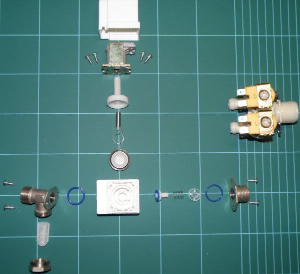
The inexpensive (£6.00) eBay devices are unsuitable for two reasons. The orifice in the servo diaphragm is far too small to remain unblocked and the actuator is within the fluid envelope (it will get jammed up with the sugary wort). Similarly, the easily available domestic appliance dual inlet solenoid valve is unsuitable due to the high pressure required to operate it and the actuator also being in the fluid envelope.
The only "full flow" devices I can find available in the UK are expensive. I have some 115V devices available which would undoubtedly work, but the intention of this post is to suggest a practical and inexpensive solution for anyone who wants to try it.
All ON/OFF valves suffer from the disadvantage of providing only a comparatively coarse control, although when operated quickly enough, the averaging of the flow would be good enough for the purpose. In this case however, the length of service before mechanical failure would be greatly reduced.
A large number of methods were considered and discarded due to cost and/or complexity.
The end results still requires a bit of work by the constructor, but nothing that should be beyond the average brewer here.
There are two basic versions, both have identical pipe work and valve structure. The difference is in the actuator - Solenoid and Servo driven. There are two methods of driving the servo.
With the solenoid version, the outputs from the relay in the PID, with a 12V power supply, drive the solenoid directly. The power supply is available for less than a fiver. The control panel described elsewhere includes all the parts necessary to make this work.
The result is:
Low cost (servo £8.49, solenoid about £11, some Silicone tubing, a few plumbing bits, piece of bent aluminium, could be a couple of bits of angle from B&Q)
Very easy to clean and replace tube
Disadvantage of servo type:
A bit of simple electronics (which could be produced by many here).
The ultimate - the servo version is crying out for an Arduino using of the shelf libraries for both the PID and Servo drive functions. I might do this next and if I get time I will post the whole project.
(It would also make sense to extend this to HLT temperature control etc etc...)
The mechanics:
Pinch valves have been proposed elsewhere on the 'net, but I have not seen a practical example, particularly with a continuously variable output, these offer both on/off and variable operation.
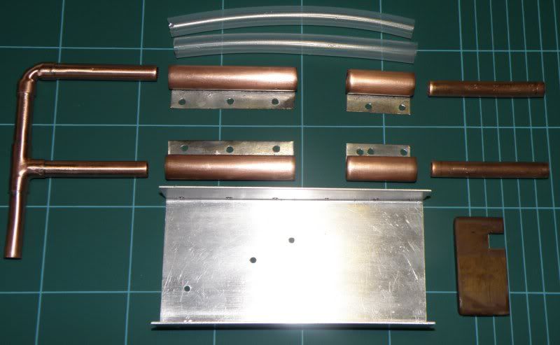
The parts:
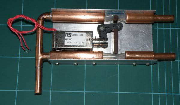
Solenoid version:
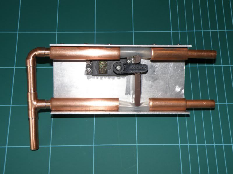
Servo version:
The 15mm pipe shown is just to locate the bits of 10mm copper pipe and the flexible tube.
Having made them this way, "P" clips would be better.
Santoprene tubing is used in peristaltic pumps (see also Ismaprene, Norprene, Marprene etc). It has a longer life expectancy than silicone, but I have not found a source for a small quantity of 9.5mm x 1.6 wall. I did try 9.5mm x 2.4mm (http://www.altecweb.com), but this is somewhat inflexible.
Silicone 10mm x 1mm: http://www.silex.co.uk/iqs/dbitemid.56/ ... _shop.html
Solenoids are available for RS etc, the one shown is http://uk.rs-online.com/web/search/sear ... &R=0349709
There are several others which would be suitable, but you might find that something like a central locking relay/motor would work well.
The servo used will be very familiar to many of you; it is used in radio controlled model cars, boats and planes. I have used a 15Kg model.
e.g. http://cgi.ebay.co.uk/HXT-15kg-high-tor ... 20b5c20e43
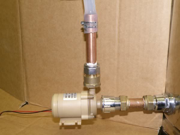
The pump is a low cost "solar" type:
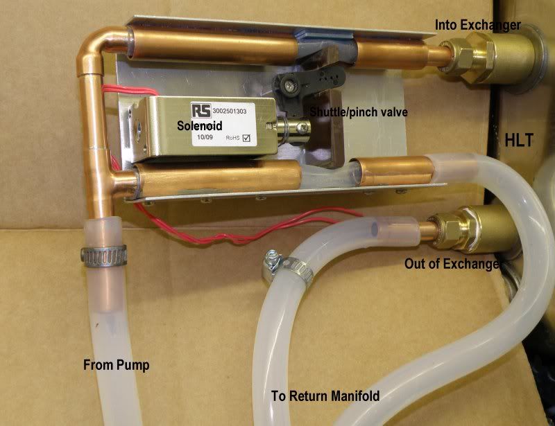
The solenoid version attached to the Heat Exchanger in the HLT:
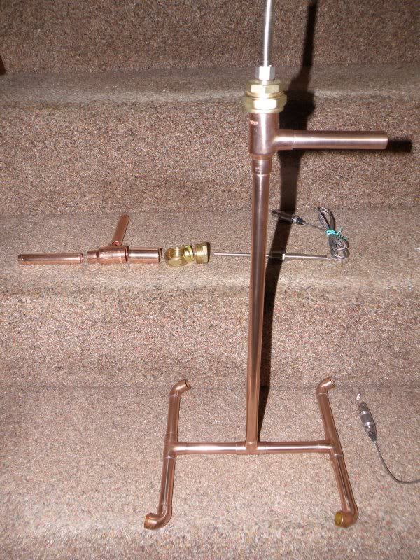
And the return manifold with the parts for the probe housing etc shown behind:
Principles of operation:
The system uses the typical temperature sensor/PID model. In most systems the PID controls a Solid State Relay which in turns controls a heating element. The ON/OFF time ratio of the element is determined by the difference between the set point of the system and the actual temperature measured.
In these examples, the PID drives a solenoid directly, or drives a servo backward and forward via a current limiter or via a simple A to D to produce an fully controllable linear mixing system.
For the first two methods, on ON/OFF time ratio is very similar to using a heater element - when the PID output is off, the solenoid/servo closes the path through the Heat exchanger. When the PID output is on, the solenoid/servo closes the bypass such that all the flow goes through the heat exchanger.
For the last method, the servo position is controlled to "mix" the wort which travels by both parts - proportionally to the PID output.
This voltage is used to control the position of the servo actuator arm which in turn varies the proportion of the Heated and Bypassed wort flow. These two flows are then combined and returned to the mash tun via the temperature sensor - simples.
Practical:
I prefer to use a PID which displays both set point and actual temperatures. These are available on eBay (as detailed and listed in the HLT-HERMS panel post). They have a relay output with normally open and normally closed contacts and a SSR output. One of these must be turned into an analogue control voltage for the servo.
In order to get a reasonably fast response time, the "Ot" should be set to minimum (2 seconds) and the SSR output used. The SSR output has an open circuit voltage of 8V and a short circuit current of 40mA.
Having investigated the use of currently available solenoid valves and in the interest of flexibility and cost I propose a new technique for use with HLT HERMS.
I have experience in the use of solenoid valves from many years ago. The market has changed considerably in some respects, but not at all in others.
The inexpensive (£6.00) eBay devices are unsuitable for two reasons. The orifice in the servo diaphragm is far too small to remain unblocked and the actuator is within the fluid envelope (it will get jammed up with the sugary wort). Similarly, the easily available domestic appliance dual inlet solenoid valve is unsuitable due to the high pressure required to operate it and the actuator also being in the fluid envelope.
The only "full flow" devices I can find available in the UK are expensive. I have some 115V devices available which would undoubtedly work, but the intention of this post is to suggest a practical and inexpensive solution for anyone who wants to try it.
All ON/OFF valves suffer from the disadvantage of providing only a comparatively coarse control, although when operated quickly enough, the averaging of the flow would be good enough for the purpose. In this case however, the length of service before mechanical failure would be greatly reduced.
A large number of methods were considered and discarded due to cost and/or complexity.
The end results still requires a bit of work by the constructor, but nothing that should be beyond the average brewer here.
There are two basic versions, both have identical pipe work and valve structure. The difference is in the actuator - Solenoid and Servo driven. There are two methods of driving the servo.
With the solenoid version, the outputs from the relay in the PID, with a 12V power supply, drive the solenoid directly. The power supply is available for less than a fiver. The control panel described elsewhere includes all the parts necessary to make this work.
The result is:
Low cost (servo £8.49, solenoid about £11, some Silicone tubing, a few plumbing bits, piece of bent aluminium, could be a couple of bits of angle from B&Q)
Very easy to clean and replace tube
Disadvantage of servo type:
A bit of simple electronics (which could be produced by many here).
The ultimate - the servo version is crying out for an Arduino using of the shelf libraries for both the PID and Servo drive functions. I might do this next and if I get time I will post the whole project.
(It would also make sense to extend this to HLT temperature control etc etc...)
The mechanics:
Pinch valves have been proposed elsewhere on the 'net, but I have not seen a practical example, particularly with a continuously variable output, these offer both on/off and variable operation.
The parts:
Solenoid version:
Servo version:
The 15mm pipe shown is just to locate the bits of 10mm copper pipe and the flexible tube.
Having made them this way, "P" clips would be better.
Santoprene tubing is used in peristaltic pumps (see also Ismaprene, Norprene, Marprene etc). It has a longer life expectancy than silicone, but I have not found a source for a small quantity of 9.5mm x 1.6 wall. I did try 9.5mm x 2.4mm (http://www.altecweb.com), but this is somewhat inflexible.
Silicone 10mm x 1mm: http://www.silex.co.uk/iqs/dbitemid.56/ ... _shop.html
Solenoids are available for RS etc, the one shown is http://uk.rs-online.com/web/search/sear ... &R=0349709
There are several others which would be suitable, but you might find that something like a central locking relay/motor would work well.
The servo used will be very familiar to many of you; it is used in radio controlled model cars, boats and planes. I have used a 15Kg model.
e.g. http://cgi.ebay.co.uk/HXT-15kg-high-tor ... 20b5c20e43
The pump is a low cost "solar" type:
The solenoid version attached to the Heat Exchanger in the HLT:
And the return manifold with the parts for the probe housing etc shown behind:
Principles of operation:
The system uses the typical temperature sensor/PID model. In most systems the PID controls a Solid State Relay which in turns controls a heating element. The ON/OFF time ratio of the element is determined by the difference between the set point of the system and the actual temperature measured.
In these examples, the PID drives a solenoid directly, or drives a servo backward and forward via a current limiter or via a simple A to D to produce an fully controllable linear mixing system.
For the first two methods, on ON/OFF time ratio is very similar to using a heater element - when the PID output is off, the solenoid/servo closes the path through the Heat exchanger. When the PID output is on, the solenoid/servo closes the bypass such that all the flow goes through the heat exchanger.
For the last method, the servo position is controlled to "mix" the wort which travels by both parts - proportionally to the PID output.
This voltage is used to control the position of the servo actuator arm which in turn varies the proportion of the Heated and Bypassed wort flow. These two flows are then combined and returned to the mash tun via the temperature sensor - simples.
Practical:
I prefer to use a PID which displays both set point and actual temperatures. These are available on eBay (as detailed and listed in the HLT-HERMS panel post). They have a relay output with normally open and normally closed contacts and a SSR output. One of these must be turned into an analogue control voltage for the servo.
In order to get a reasonably fast response time, the "Ot" should be set to minimum (2 seconds) and the SSR output used. The SSR output has an open circuit voltage of 8V and a short circuit current of 40mA.