


HLT HERMS - Control Panel construction:
This panel is designed for no more than 10 Amps - i.e. one 2.4KW kettle element or similar.
The constraints are due to the Temperature Controller internal relay. Thus the mains IN/OUT connector is suitable for 10A maximum. If you need more, you should use a relay or SSR and higher rated switches, cable and connectors (some ideas below).
If you are not absolutely sure of your ability to build and if necessary modify electronics of this sort, please ask someone who can.
Please let me clarify one point about the difference between Simple Temperature Controllers and PID controllers when applied to HLTs. A Simple Temperature Controller can keep the liquor temperature within 0.25C quite easily - it depends on the hysteresis you set. It is ideal for the control of a large mass of liquor and it will result in the minimum heating time because it is 100% on until it reaches the set temperature. A PID controller is overkill in this application - but use one by all means if you have cash to spare.
Please read the "Background and tests" posting to see the actual, measured results obtained with a STC1000 and no stirring. If the HLT is insulated, or if the liquor remains static for a significant time, stratification may occur - however, this will not happen while the HLT HERMS is running.
The switch "HERMS Power" is fitting but not yet used. It allows a second heat exchanger to be brought into service e.g. for brews of 100-200 litre.
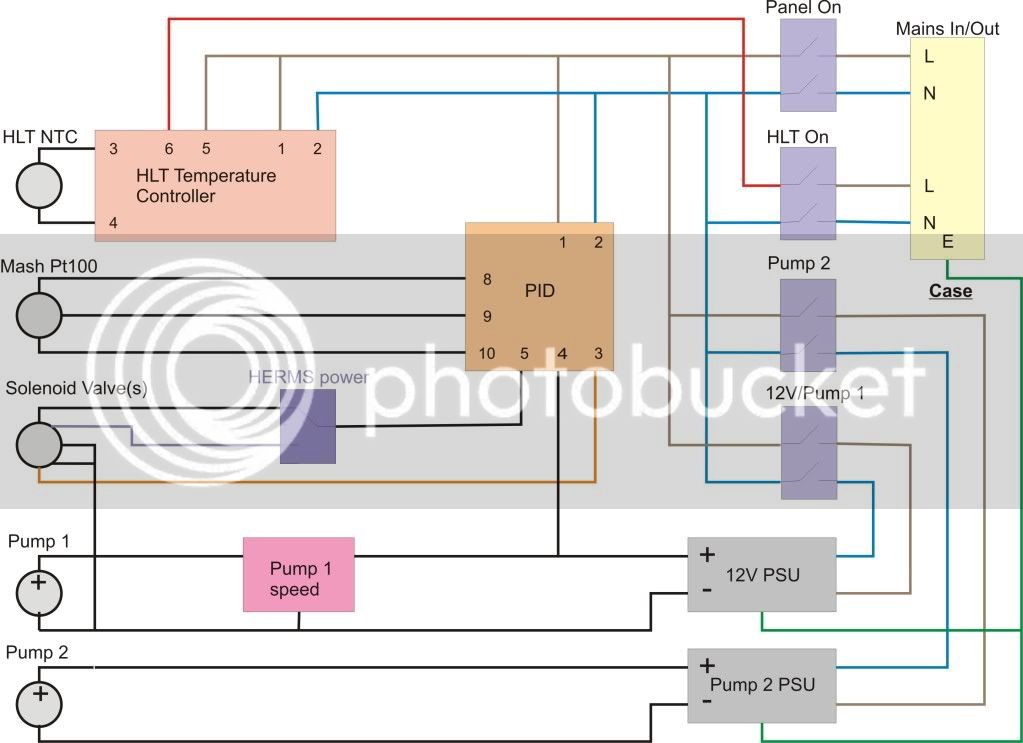
Control Panel circuit diagram:
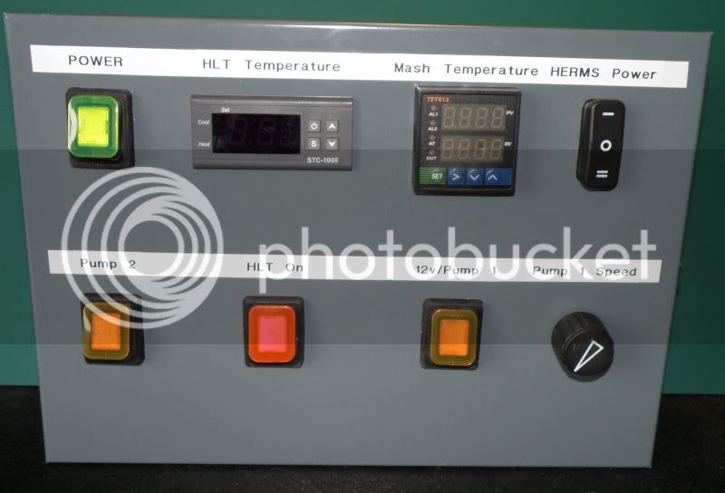
Control Panel front:
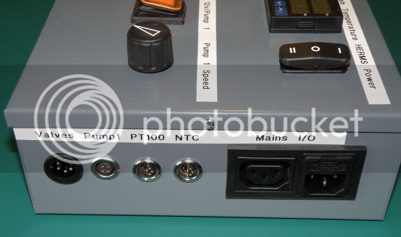
Control Panel side with connectors:
Control Panel internal parts and wiring:
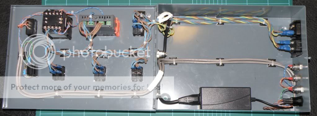
The Power Supply for the second pump is not fitted in the pictures for clarity.
The metal case is earthed with an additional earth to the hinged front panel. There are no additional exposed conductive parts, but if yours has any, they need to be electrically bonded to the metal case. Rigid plastic cases (e.g. ABS but not polyethylene) are suitable if mechanically secured e.g. to a wall or brewery frame. Wood is unacceptable as it can become damp or even soaked and as you all know, electricity and water do not mix. Covers, panels and lids etc should be fixed with screws, not push-on or clip-on.
If you use a non-metal case, all fixings and brackets which pass through the casing and are externally exposed must be individually earthed for your, and your children's safety. This further implies that the casing must be rigid - polyethylene, polypropylene, wood etc will deform under pressure and the earth bonding will fail.
The mains and low voltage wiring are separated and secured for safety; if a wire should come loose it will not cause a short between live and LV parts.
(These last two points are covered by the design consideration of "first fault/failure").
The internal mains wiring is 1.0 mm sq apart from the double insulated routes from the 12V/Pump(s) switches to their respective power supplies which is 0.75 mm sq. The 1.0 mm sq wiring used here is high temperature rated and I suggest using 1.25 or 1.5 mm sq if using standard PVC insulated cable.
(Standard PVC 1.0 mm sq is right on its limit at 10A with 4 bunched conductors - ref. IEE Wiring regulations).
For the low voltage wiring, Cat 5E cable is used for convenience, cost and neatness - this should be the stranded type used for patch leads, not single cored structured cabling (it needs flexibility when the door is opened and closed).
Some of the parts used: (not the cheapest sources)
Sensors for test only LM35DT http://uk.rs-online.com/web/search/sear ... R=535-9458
Sensors for test only LM35CAZ http://uk.rs-online.com/web/search/sear ... R=533-5878
Case http://uk.rs-online.com/web/search/sear ... &R=231-970
3 position switch http://uk.rs-online.com/web/search/sear ... R=706-4023
Illuminated switches http://uk.rs-online.com/web/search/sear ... R=456-1694
6-PIN connectors http://uk.rs-online.com/web/search/sear ... R=261-5806
(Strictly the wrong sex, but ok at 12 volts)
Connectors for probes and motors - Maybe DIN Audio or similar (I have a box full of the Lemo ones shown)
Mains IN/OUT http://uk.rs-online.com/web/search/sear ... R=211-1017
12volt 4A PSU http://cgi.ebay.co.uk/12V-4A-LCD-Monito ... 4aa6039836
Temperature controller (HLT) http://cgi.ebay.co.uk/ws/eBayISAPI.dll? ... 0609566283
PID http://cgi.ebay.com/NEW-DUAL-DIGITAL-F- ... 45f9f89046
HLT probe (NTC) http://uk.rs-online.com/web/search/sear ... &R=0461159
PT100 probe http://cgi.ebay.co.uk/Thermocouple-Temp ... 230eb668ca
Plumbing parts - mainly http://www.screwfix.com
Not used, but suitable for operation to 20A:
Mains connectors:
http://cpc.farnell.com/bulgin/px0596-63 ... dp/CN08375
http://cpc.farnell.com/bulgin/px0599/ma ... dp/CN08372
SSR http://cgi.ebay.co.uk/ws/eBayISAPI.dll? ... SA:GB:1123
Fitted onto e.g. http://uk.rs-online.com/web/search/sear ... &R=5075194
Please note: Fins vertical in free-flowing air at an ambient of up to 50C, 25A, check thermal de-rating curve.
Adequately scaled heatsinks are vital for safe operation. You could well need an additional fan if the heatsink is mounted inside the case. Fins should always be vertical and in free air - think about it - if you put the heatsink inside a sealed box, the box will get hot and the heatsink hotter.
Safety issues:
Unlike some forum contributors, I have not taken exams for IEE Regs, Part P etc.
Instead, from the early 1980's to the mid 2000's, in conjunction with many other consulting engineers, I was writing parts of these standards and exams, including IEC601, BS5750 and the above. Therefore I know why we draw up specifications - not just the details but the reasoning behind them.
If at all possible, have your completed panel tested by a competent electrical engineer using a calibrated and checked PAT device (Portable Appliance Testing).
Most of the forums posts are light hearted, entertaining and fun, this one is not.
Killing yourself or your kids by ignoring safety or shoddy workmanship is suicide or "manslaughter by gross negligence" - look it up.
This panel is designed for no more than 10 Amps - i.e. one 2.4KW kettle element or similar.
The constraints are due to the Temperature Controller internal relay. Thus the mains IN/OUT connector is suitable for 10A maximum. If you need more, you should use a relay or SSR and higher rated switches, cable and connectors (some ideas below).
If you are not absolutely sure of your ability to build and if necessary modify electronics of this sort, please ask someone who can.
Please let me clarify one point about the difference between Simple Temperature Controllers and PID controllers when applied to HLTs. A Simple Temperature Controller can keep the liquor temperature within 0.25C quite easily - it depends on the hysteresis you set. It is ideal for the control of a large mass of liquor and it will result in the minimum heating time because it is 100% on until it reaches the set temperature. A PID controller is overkill in this application - but use one by all means if you have cash to spare.
Please read the "Background and tests" posting to see the actual, measured results obtained with a STC1000 and no stirring. If the HLT is insulated, or if the liquor remains static for a significant time, stratification may occur - however, this will not happen while the HLT HERMS is running.
The switch "HERMS Power" is fitting but not yet used. It allows a second heat exchanger to be brought into service e.g. for brews of 100-200 litre.
Control Panel circuit diagram:
Control Panel front:
Control Panel side with connectors:
Control Panel internal parts and wiring:
The Power Supply for the second pump is not fitted in the pictures for clarity.
The metal case is earthed with an additional earth to the hinged front panel. There are no additional exposed conductive parts, but if yours has any, they need to be electrically bonded to the metal case. Rigid plastic cases (e.g. ABS but not polyethylene) are suitable if mechanically secured e.g. to a wall or brewery frame. Wood is unacceptable as it can become damp or even soaked and as you all know, electricity and water do not mix. Covers, panels and lids etc should be fixed with screws, not push-on or clip-on.
If you use a non-metal case, all fixings and brackets which pass through the casing and are externally exposed must be individually earthed for your, and your children's safety. This further implies that the casing must be rigid - polyethylene, polypropylene, wood etc will deform under pressure and the earth bonding will fail.
The mains and low voltage wiring are separated and secured for safety; if a wire should come loose it will not cause a short between live and LV parts.
(These last two points are covered by the design consideration of "first fault/failure").
The internal mains wiring is 1.0 mm sq apart from the double insulated routes from the 12V/Pump(s) switches to their respective power supplies which is 0.75 mm sq. The 1.0 mm sq wiring used here is high temperature rated and I suggest using 1.25 or 1.5 mm sq if using standard PVC insulated cable.
(Standard PVC 1.0 mm sq is right on its limit at 10A with 4 bunched conductors - ref. IEE Wiring regulations).
For the low voltage wiring, Cat 5E cable is used for convenience, cost and neatness - this should be the stranded type used for patch leads, not single cored structured cabling (it needs flexibility when the door is opened and closed).
Some of the parts used: (not the cheapest sources)
Sensors for test only LM35DT http://uk.rs-online.com/web/search/sear ... R=535-9458
Sensors for test only LM35CAZ http://uk.rs-online.com/web/search/sear ... R=533-5878
Case http://uk.rs-online.com/web/search/sear ... &R=231-970
3 position switch http://uk.rs-online.com/web/search/sear ... R=706-4023
Illuminated switches http://uk.rs-online.com/web/search/sear ... R=456-1694
6-PIN connectors http://uk.rs-online.com/web/search/sear ... R=261-5806
(Strictly the wrong sex, but ok at 12 volts)
Connectors for probes and motors - Maybe DIN Audio or similar (I have a box full of the Lemo ones shown)
Mains IN/OUT http://uk.rs-online.com/web/search/sear ... R=211-1017
12volt 4A PSU http://cgi.ebay.co.uk/12V-4A-LCD-Monito ... 4aa6039836
Temperature controller (HLT) http://cgi.ebay.co.uk/ws/eBayISAPI.dll? ... 0609566283
PID http://cgi.ebay.com/NEW-DUAL-DIGITAL-F- ... 45f9f89046
HLT probe (NTC) http://uk.rs-online.com/web/search/sear ... &R=0461159
PT100 probe http://cgi.ebay.co.uk/Thermocouple-Temp ... 230eb668ca
Plumbing parts - mainly http://www.screwfix.com
Not used, but suitable for operation to 20A:
Mains connectors:
http://cpc.farnell.com/bulgin/px0596-63 ... dp/CN08375
http://cpc.farnell.com/bulgin/px0599/ma ... dp/CN08372
SSR http://cgi.ebay.co.uk/ws/eBayISAPI.dll? ... SA:GB:1123
Fitted onto e.g. http://uk.rs-online.com/web/search/sear ... &R=5075194
Please note: Fins vertical in free-flowing air at an ambient of up to 50C, 25A, check thermal de-rating curve.
Adequately scaled heatsinks are vital for safe operation. You could well need an additional fan if the heatsink is mounted inside the case. Fins should always be vertical and in free air - think about it - if you put the heatsink inside a sealed box, the box will get hot and the heatsink hotter.
Safety issues:
Unlike some forum contributors, I have not taken exams for IEE Regs, Part P etc.
Instead, from the early 1980's to the mid 2000's, in conjunction with many other consulting engineers, I was writing parts of these standards and exams, including IEC601, BS5750 and the above. Therefore I know why we draw up specifications - not just the details but the reasoning behind them.
If at all possible, have your completed panel tested by a competent electrical engineer using a calibrated and checked PAT device (Portable Appliance Testing).
Most of the forums posts are light hearted, entertaining and fun, this one is not.
Killing yourself or your kids by ignoring safety or shoddy workmanship is suicide or "manslaughter by gross negligence" - look it up.
