Automatic Underback

The Homebrew Forum

Help Support The Homebrew Forum:

This site may earn a commission from merchant affiliate links, including eBay, Amazon, and others.

beer taster

Well-Known Member
Joined
Nov 5, 2008
Messages
118
Reaction score
0
Location
Hemel
Hi All
I'm currently in the process of tinkering with the brewery. Just added a Valentines Arm, now planning an automatic underback so I can fly sparge using the V-Arm and pump the wort from an underback to the boiler.
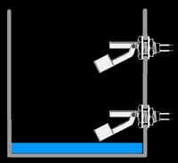
I plan to use a Stainless pot (not sure what size probably 5-10L) as the underback and put 2 float switches in the pot. When the wort reaches the uppermost switch it turns on the pump and pumps the wort to the boiler, when the level drops below the lower switch it turns off the pump.

underback-float-sw.jpg


The float switches I will be using can be found HERE

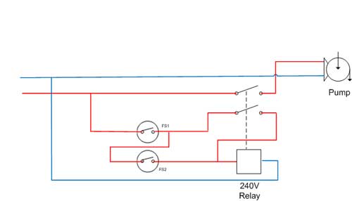
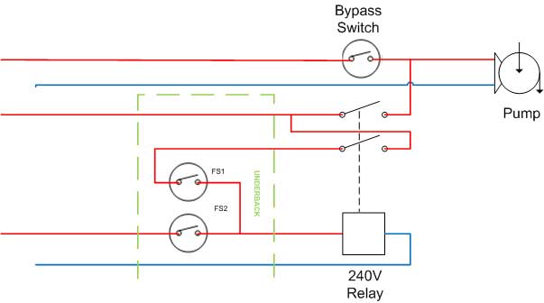
Below is my planned wiring of the float switches. When the wort level in the underback hits FS1 nothing happens. When it hit FS2 the pump is turned on and will stay on until the level drops below FS1 the pump will turn off.
Will this work. :hmm:
underback-wiring.jpg
 
That won't work, FS2 will turn the pump on but once below the float level it will switch the pump back off?
I Haven't got time at the minute to work this out will have a think tommorow and post in the evening if no one else come up with an answer before then :hmm:

Edit hang on is the underback drawn upside down is Fs1 the bottom level or the top level? I still can't see it working?
 
It won't work. I'll tell you why tomorrow when i'm on the computer and not my phone. You need a latch in there.
 
I was just going to say a latching relay is needed, also will the bottom float switch take being submerged ? as with float switches they want to float not be under the waterline? just think it may overstress the linkage?
 
Tis no prob for a magnetic float switch like a Mobrey
May be a bit expensive for the job, I seen them a lot in Sh1t tanks at sea and also in boiler applications. There must be an easier solution to the problem, not sure there even is a problem, use a gate/ball valve and hand regulate, unless your planning to leave it run unattended :hmm:
 
muddydisco said:
will the bottom float switch take being submerged ? as with float switches they want to float not be under the waterline? just think it may overstress the linkage?
I hope so, i did check and it says they can be totally submerged.
Bru4u said:
use a gate/ball valve and hand regulate, unless your planning to leave it run unattended :hmm:
I don't plan to leave it unattended, but I do want to reduce the amount of fiddling about balancing ball valves / pumps.
 
The float switches are fine. The problem is the logic to control it.

I'm building exactly the same at the moment but i'm using a pic to control it. I need to control a solenoid valve but it will be able to control a relay too. I'm quite happy to build two circuits if you want one. I'm just waiting for my mosfets to arrive. Probably be about a tenner including postage. You will need 24v dc available.
 
Looking at the spec for the switch they can be used for normally open or normally closed contact,so a standard motor control circuit should do the trick,make fs1 normally closed and fs2 normal open.
motor.jpg
 
themadhippy said:
Looking at the spec for the switch they can be used for normally open or normally closed contact,so a standard motor control circuit should do the trick,make fs1 normally closed and fs2 normal open.
Hi Mad Hippy - I'm blaming the beer but I cannot work out the logic. :wha: If FS1 is normally closed then when the liquid reaches FS1(the lower level in the underback), the switch will open and the relay will never operate.
jamesb said:
I'm quite happy to build two circuits if you want one. You will need 24v dc available.
James, thanks for your kind offer, unfortunately I don't have a 24V supply and I'm not going to let this beat me....... Well not for a while :oops:
 
When the upper limit float switch activates the relay, one of the relay contacts must hold the relay operated. (Pump operated)
The relay is released when the lower limit float switch breakes the holding circuit. (Pump released)
I would also recommend that the by-pass switch is non-locking. (stops the pump running dry)
 
If I were you I would look for an automatic condensate pump, I use a march may condensate pump as an automatic underback and it works a treat, stainless steel box pump parts are all foodsafe and will take 120 deg c temp, and the float switch is allready fitted and wired in, all I needed to do was put a plug on it and fit the outlet pipework, it works a treat.

I have just done a search on fleabay, no march mays but this would probably do the job

http://cgi.ebay.co.uk/Aspen-Macerator-C ... 618wt_1165

It looks very very similar to mine & a bargain at £70.00


UP
 
unclepumble said:
If I were you I would look for an automatic condensate pump,
Now that's an interesting idea :hmm: and I thought a Macerator was only used on saniflo toilets :shock:
evanvine said:
Possible schematic diagram
Thanks evanvine, - float switches and relay have arrived so I'm going to do some experimenting tomorrow to see what will and won't work.
 
If FS1 is normally closed then when the liquid reaches FS1(the lower level in the underback), the switch will open and the relay will never operate
Fs1 will close contacts once the liquid reaches it and remain closed until the liquid falls below it ,when fs2 is trigered it will pull in the relay ,which due to the self hold circuit,stays engaged until the level drops to allow fs1 to opens
 
themadhippy said:
Fs1 will close contacts once the liquid reaches it and remain closed until the liquid falls below it ,when fs2 is trigered it will pull in the relay ,which due to the self hold circuit,stays engaged until the level drops to allow fs1 to opens
Thanks i think we have a consensus, so I will test tomorrow night
 
On mine the float travels up and down a rod and makes a micro switch above the liquid level, it is just a simple make or break circuit. Switch made pump runs switch not made pump doesn't run. as long as the switch is made and unmade above the pump inlet there is no need for a second float switch.


UP
 
Hi Guys
Thanks for all your help, experimented this evening and ended up with circuit below. Only tested it with a light but it seems to works OK. Now need to make a prototype out of a plastic bucket before getting the stainless pot.

Mark

underback-wiring1.jpg
 
Glad you have got your wiring sorted Mark, but if you would humour an old brewer, what is the purpose of your "underback"?
I've always gone directly from boiler to FV, or am I missing the point, especialy as you are going to make it from, SS?
 
Underback is small pot to collect the runnings out of the tun then the pump sucks from this. My system you seen hasn't got one so I have to balance the flow of the pump so it doesn't suck the grist to the bottom of the tun.
I Do like the look of this though and if all works out well, I may go this way when I upgrade.
 

Latest posts

Back
Top