Reading my last post I understand why I should not be posting after midnight... Ofcourse I understood the next morning...

Thanks to Loetz (PM) and mixale (scan), in the versions of the Manual I have, the settings are only described in crude chinese-english text style.
The extended Manual I referred to was one I found by Google, the small piece of paper contained in the Package did not describe anything except setting the SV value.
In the meantime I did some comparision between the old ones I had in stock and some newly ordered regulators. It seems while changing to lead free solder process the PCB layout was slightly changed. (Found no new board with leaded solder and vice versa)
- A Useless Solder Bridge in the power trace to relay working contact has disappeared
- Some spare holes for using many different relay types have disappeared
- One of the more bewildering: Three SMD resistors have been replaced by 1/8W wired parts (No, it's not related to power dissipation, I measured. And no, they did not completely avoid SMD process by this, there are some SMD parts still used on the same PCB, maybe they are preparing to remove SMD parts on one of the two boards in a future revision.)
- At least one metal film resistor in the display group has been changed to a carbon film type
- The ribbon cable between the boards is no longer split at the one end, the needless unconnected pad in the center of the line was removed.
The clean conversion from relay output to Voltage output by comparing the original boards is as follows:
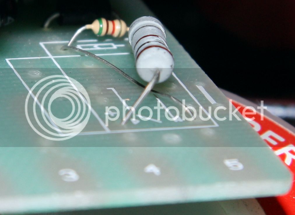
- Bridge the relay coil pads by a 5.1kR 1/8 or 1/4W
- Route a plain wire from the left coil pad to the right output pad
- Route a 100R 1 or 2W type from the right coil pad to the left output pad
- YES on the 'relay coil' side there are two wires in each hole, even on the older ones which have plenty of spare pads and holes
Right and left as seen from the component side.
This is a picture of the correct configuration for voltage output. (Original chinese quality with shattered resistor coating... :wha: )
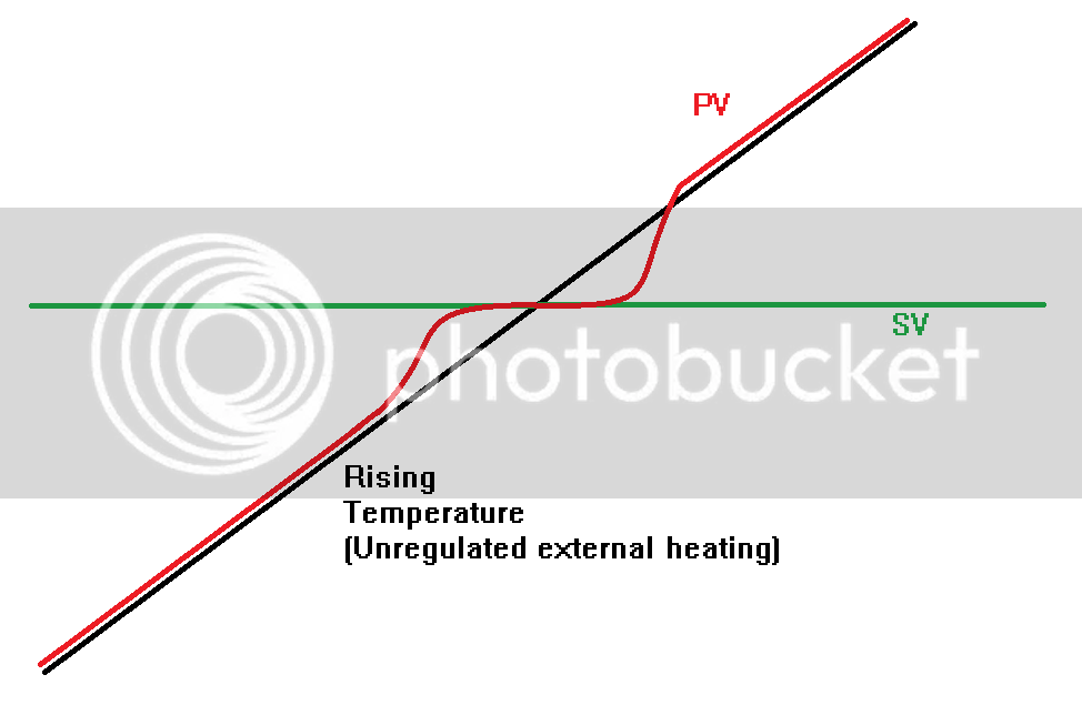
Here is the graph from my upper posting, which has been lost in the abyss of the previously chosen free image hoster.
edit:
For the conversion to voltage output... remove the relay first... makes job much easier... :mrgreen: