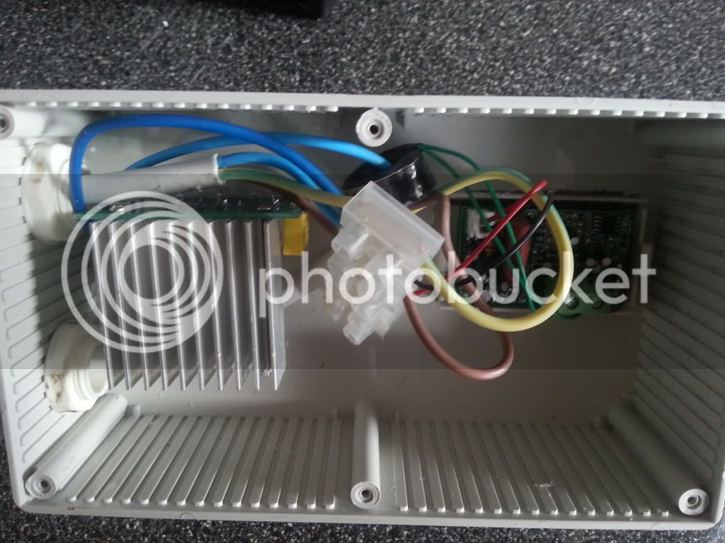
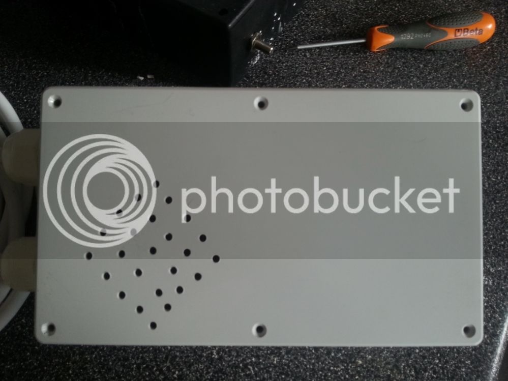
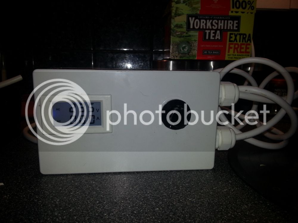
My new Voltage controller :)

The Homebrew Forum

Help Support The Homebrew Forum:

This site may earn a commission from merchant affiliate links, including eBay, Amazon, and others.
Interesting - on second attempt the video worked fine. Do you have more details on how the kettle is connected etc?
Circuit diagram maybe?
 
Hm, handy. Fancy writing up a longer post on the parts and build? Or is there a reliable guide out there already?
 
will get a more detailed post up once the daughter has stopped playing up, lol.

Will also get a list of parts needed to do this too.
 
List of Parts -

Maplin ABS box
Triac based voltage regulator http://www.ebay.co.uk/itm/221122548000
Digital Volt/Amp meter http://www.ebay.co.uk/itm/281052386403
3 Metres of Flex Cable
Female Plug Socket
Male Plug Socket
2 Cable Glands
1 Electrical Choc Block

Cut the hole out for the display, for this i got the dremel out and cut the hole to shape, then added another hole for the regulator to stick though. I then got a 20mm hole saw for the cable glands to fit through.

I then fitted all the parts in their place and started on the wiring side of things. I connected a male plug to the Power In and connected this to the choc block connector, i then wired up a female plug socket and connected the neutral and earth to the choc block leaving the live going to the regulator. I got another live wire and connected this from the other terminal on the regulator to the live in on the choc block connector.
The display needed wiring up to the live and neutral with the transformer ring running around the Live wire coming from the regulator to the female plug.

A few pics of the internals here. Note i put some holes in the back to aid ventilation.

20130405_104338_zps690560d7.jpg


20130405_104353_zps31857f7a.jpg


20130404_194316_zpsb527f90a.jpg
 
Thanks for the write-up!

Does my amateurish diagram look about right?!

[edit] Diagram updated, read on...
 
yep thats right other than the colours, red is brown and brown is blue in your diagram :)

Just been told that i should have the live to the regulator not the neutral, so can you alter the diagram to reflect this :)
 
Cyclops said:
yep thats right other than the colours, red is brown and brown is blue in your diagram :)

Just been told that i should have the live to the regulator not the neutral, so can you alter the diagram to reflect this :)

How's this? :)

Voltage_Reg.png
 
Sorry for posting on an old post, but...

Shouldn't the display be connected after the regulator? At the moment it is looking like the voltage display will just be your mains input voltage. If you take a live from the out side of the regulator it should show you the voltage to the boiler. Amps will read the same either side though (bar the load placed by the voltage regulator heating up).
 
krazypara3165 said:
Is this to control the power of the heating element e.g so its easier to set a temp?

Sorry I only answered part of your question. Yes it will control the power to the element, but this is not what you would use to control the temp. For that you would use a thermostat. You would use this set up to control the amount of power supplied to the element when the wort is boiling. A gentle is 100C and a massively violent boil is 100C, so a temperature solution will not control the intensity of the boil, that is where Cyclop's device comes in.
 
Ahhhh so for example you would use the thermostat to control the temp but for the boil you would use the voltage controller to endue the boil is not OTT
 

Latest posts

Back
Top